Image heating apparatus
a heating apparatus and image technology, applied in the direction of electric/magnetic/electromagnetic heating, electrographic process, instruments, etc., can solve the problems of reducing the glossiness at the central portion of the image, difficult to make the fixing film corresponding to the heat roller to have an inverse crown shape, and wrinkling at the paper at the fixing nip part, so as to reduce the wrinkles of the recording material
- Summary
- Abstract
- Description
- Claims
- Application Information
AI Technical Summary
Benefits of technology
Problems solved by technology
Method used
Image

Examples
first embodiment
[0036] (First Embodiment)
[0037] (1) Example of Image Forming Apparatus
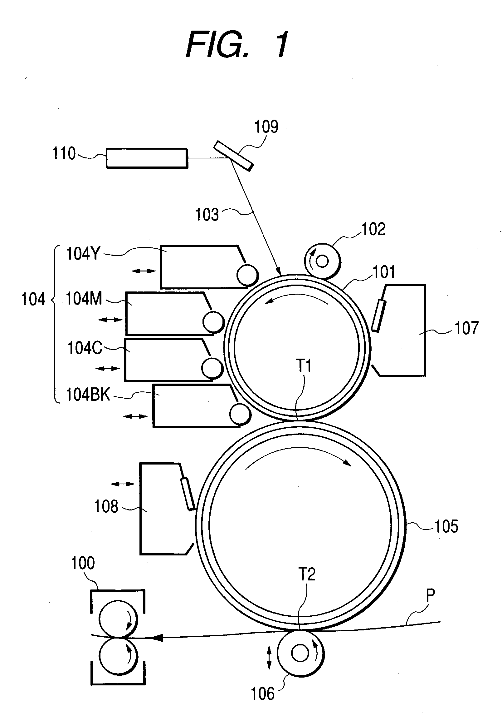
[0038] FIG. 1 is a schematic structural view of an example of an image forming apparatus. The image forming apparatus of the present example is an electrophotographic color printer.
[0039] Reference numeral 101 is a photosensitive body drum (image bearing body) formed from an organic photosensitive body or an amorphous silicon photosensitive body, and is rotation-driven at a predetermined conveying speed (peripheral velocity) in the counterclockwise direction shown by the arrow. Further, the photosensitive body drum 101 is subjected to an charging processing, which has a predetermined polarity and whose electric potential is uniform, by an charging roller 102 in the rotating process.
[0040] Next, the charging processed surface is subject to scanning exposure processing of object image information by laser light 103 outputted from a laser optical box (laser scanner) 110. The laser optical box 110 outputs the laser li...
second embodiment
[0129] (Second Embodiment)
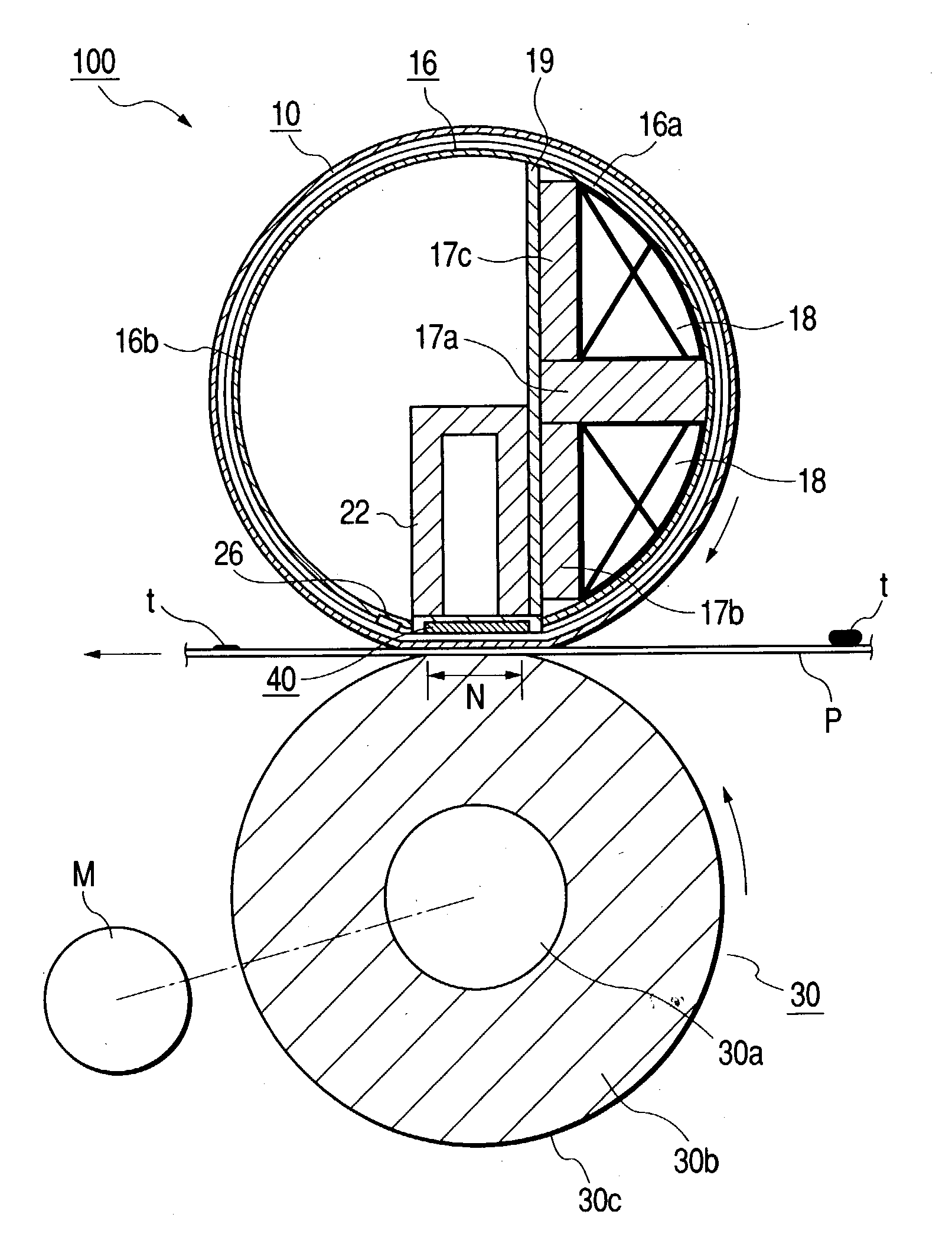
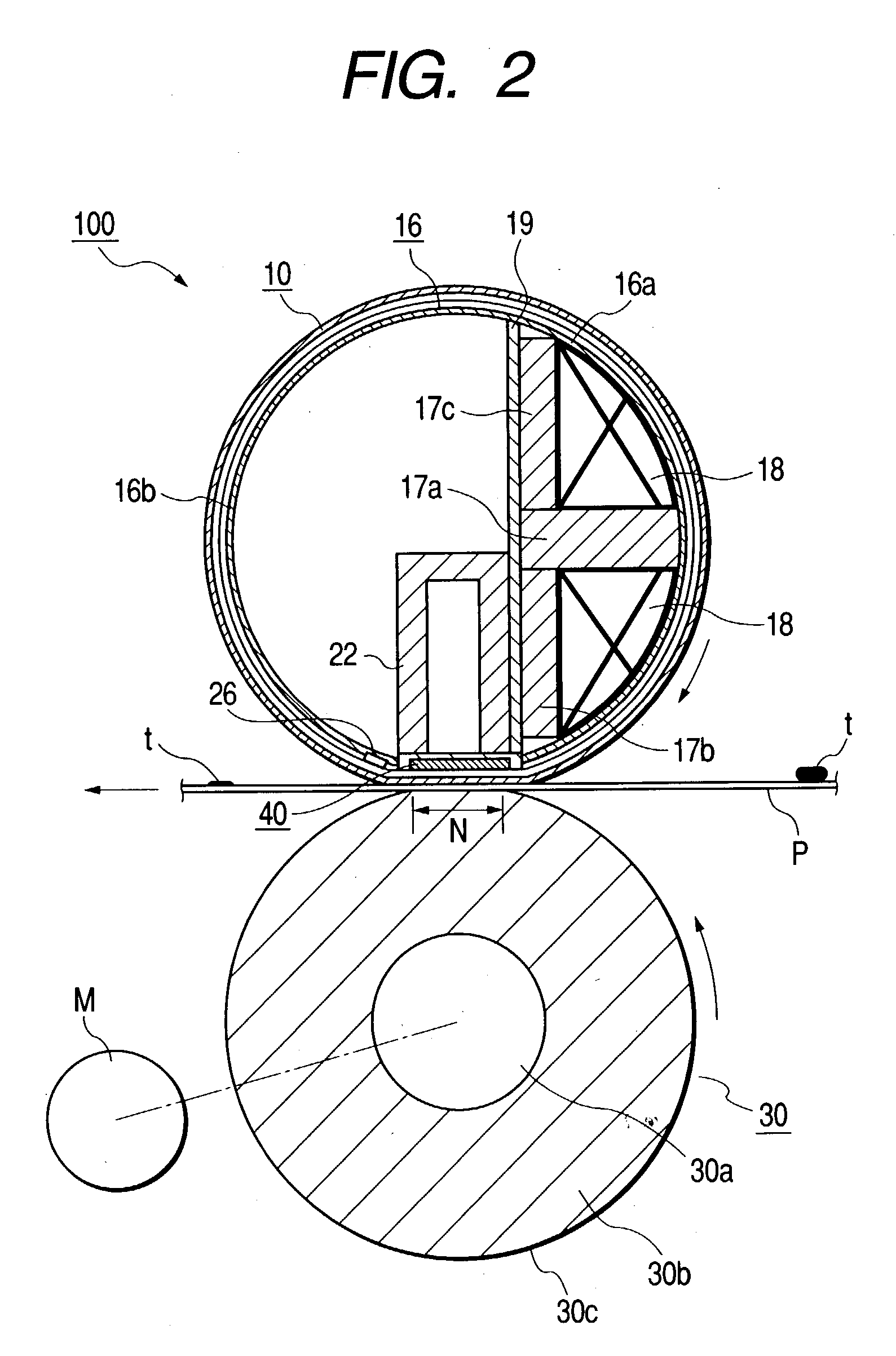
[0130] FIG. 12 is a cross-sectional model view of main portions of an image heating fixing apparatus of the present embodiment.
[0131] Reference numeral 16c is a heat-resistant / heat-insulating film guide which is shaped as a trough whose cross-section is substantially circular arc shaped. Reference numeral 12 is a ceramic heater serving as a heating body, and is fixed and supported by being fit into a groove portion which is formed and provided along the guide longitudinal direction at a substantially central part of the lower surface of the film guide 16c. In the present embodiment, the heater 12 corresponds to the sliding member.
[0132] Reference numeral 11 is a cylindrical or endless-shaped, and heat-resistant fixing film having a metal layer. The fixing film 11 is loosely fitted on the exterior of the film guide 16c.
[0133] As the base layer of the fixing film 11, by using a metal film having higher strength as the base layer, the rigidity of the fixing fi...
PUM
 Abstract
Description
Claims
Application Information
 - R&D
- Intellectual Property
- Life Sciences
- Materials
- Tech Scout
- Unparalleled Data Quality
- Higher Quality Content
- 60% Fewer Hallucinations
Browse by: Latest US Patents, China's latest patents, Technical Efficacy Thesaurus, Application Domain, Technology Topic, Popular Technical Reports.
© 2025 PatSnap. All rights reserved.Legal|Privacy policy|Modern Slavery Act Transparency Statement|Sitemap|About US| Contact US: help@patsnap.com