
Gas generator for air bag and air bag apparatus

a gas generator and air bag technology, applied in the direction of pedestrian/occupant safety arrangement, vehicular safety arrangment, vehicle components, etc., can solve the problems of difficult to equalize the pressure in the housing, inability to properly control, and the effect of reducing the burn rate of the agen

Inactive Publication Date: 2003-08-28
DAICEL CHEM IND LTD
View PDF2 Cites 21 Cited by
  • Summary
  • Abstract
  • Description
  • Claims
  • Application Information

AI Technical Summary

Benefits of technology

[0010] Also, the present invention provides a gas generator for an air bag adjusting its operation performance at a plurality of stages, which can exhibit its function securely, suppresses the entire size of a container, and has a simple structure to be manufactured and a reduced weight.
[0027] Such a closing means as a seal tape is not for adjusting the maximum internal pressure (hereinafter, referred to as "maximum internal combustion pressure") in the housing when the gas generating agent is burnt. That is, in the gas generator of the present invention, the maximum internal combustion pressure at the time of combustion of the gas generating agent is adjusted by an opening area of the gas discharging port. As a result, even after the seal tape is ruptured, the internal pressure of the housing can be adjusted according to the relationship between an opening area and combustion performance of the gas generating agent. Also, it is preferable that the closing means (particularly, in case of a seal tape) has a moisture-proof function for preventing moisture from entering the housing. In the present invention, however, when a moisture-proof means is applied to a constituent element which requires moisture-proof like the gas generating agent, the closing means may be satisfactory only to have their rupturing pressures adjusted at a plurality of stages. As such an additional moisture-proof means, for example, in case of the gas generating agent, there is a means such as wrapping the agent with a moisture-proof sheet.
[0029] In the gas generator of the present invention, by the above-described constitution, even if the actuation environment temperature of the gas generator is different, a change in internal pressure of the housing can be suppressed, and combustion of the gas generating agent can be stabilized.
[0030] Further, in the multi-stage type gas generator in which a plurality of combustion chambers are provided in a housing, and gas generating agents in the respective combustion chambers can be ignited / burnt simultaneously or independently with time lags by different ignition means, by providing at least two kinds of gas discharging ports having different pressures for opening, it is possible to equalize the pressure in the housing (hereinafter, referred to as "internal combustion pressure") at the time of combustion of the gas generating agents to stabilize the combustion performance.
[0036] Also, even in case of only one combustion chamber provided in the housing, only a gas discharging port having larger opening area is opened when an external environment temperature at the time of actuation of the gas generator is low, and besides the gas discharging port whose opening area is large, and a gas discharging port having smaller opening area is opened as well as a gas discharging port having larger opening area, when an external environment temperature at the time of actuation of the gas generator is at room temperature or high, so that a more stable internal combustion pressure can be obtained.
[0041] Also, in a gas generator whose operation performance is adjusted in a plurality of stages, there is realized a gas generator for an air bag which exhibits its function securely while suppressing the entire size of a container, and achieving a simple structure and a manufacturing easiness as well as weight reduction.

Problems solved by technology

That is, it is difficult to equalize the pressure in the housing (hereinafter, referred to as "an internal combustion pressure") and to stabilize the combustion performance when the gas generating agent is burnt.
In such a gas generator, however, since the ratios of a surface area of the gas generating agent burnt at the respective stages and an area of the gas discharging port for controlling the combustion are not preferable in all cases, a proper control can not be made such that the internal pressure in the housing is too low in combustion at the first stage or it is too high in combustion at the second stage, and therefore, further improvement is required for achieving control securely.
However, when the second gas generating agent is burnt with a delay of about 30 milliseconds or so, the combustion gas of the first gas generating agent is discharged in the meantime, the internal combustion pressure when the second gas generating agent is burnt becomes slightly lower, so that the optimal combustion environment for burning of the second gas generating agent can not be achieved.
Accordingly, when one kind of gas discharging ports are opened simultaneously from the beginning, it becomes difficult to cover all the combustion modes.

Method used


Image

  • Gas generator for air bag and air bag apparatus
  • Gas generator for air bag and air bag apparatus
  • Gas generator for air bag and air bag apparatus

Examples


embodiment 1

[0062] Embodiment 1

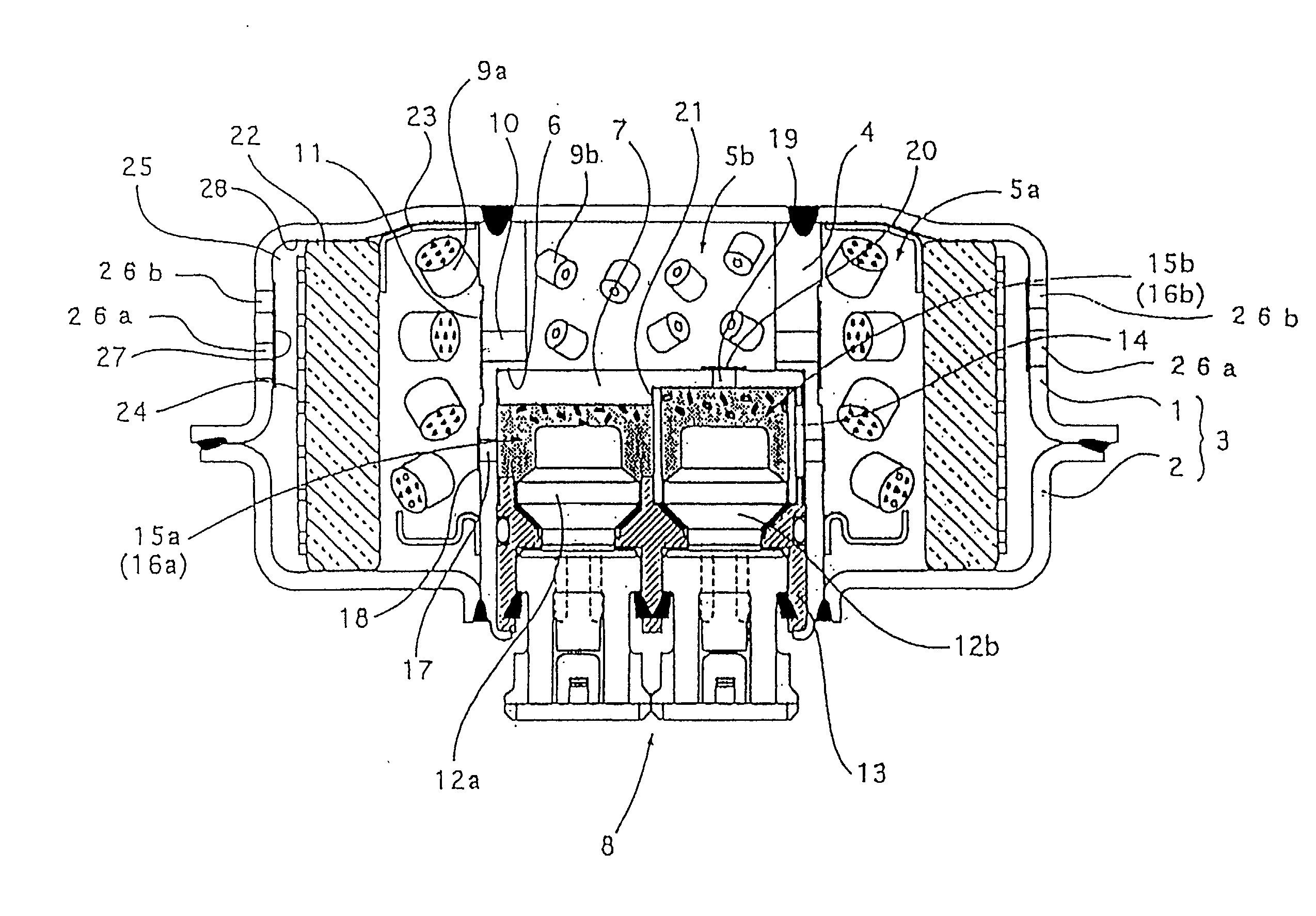
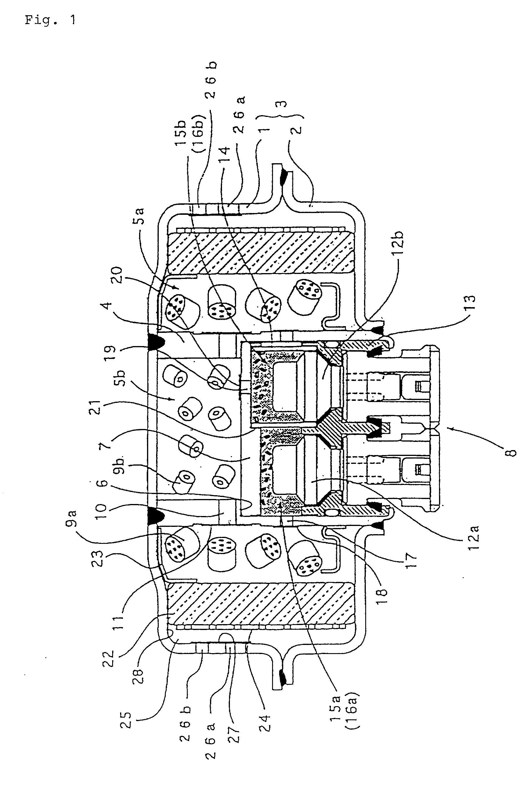
[0063] FIG. 1 is a vertical cross sectional view of a gas generator according to a first embodiment of the present invention. FIG. 1 shows a structure particularly suitable for a driver's side gas generator.

[0064] The gas generator comprises a housing 3 formed by joining a diffuser shell 1 provided with gas discharging ports and a closure shell 2 to form an inner accommodating space. The gas generator is provided with an inner cylindrical member 4 formed in a substantially cylindrical shape and arranged in the housing 3, thereby forming a first combustion chamber 5a outside the inner cylindrical member 4. Further, a stepped notch portion is provided on an inside surface of the inner cylindrical member 4, and a partitioning member 7, formed in a substantially flat circular shape, is arranged in the stepped notch portion 6. The partitioning member 7 further partitions an inner portion of the inner cylinder into two chambers to form a second combustion chamber 5b in ...

embodiment 2

[0086] Embodiment 2

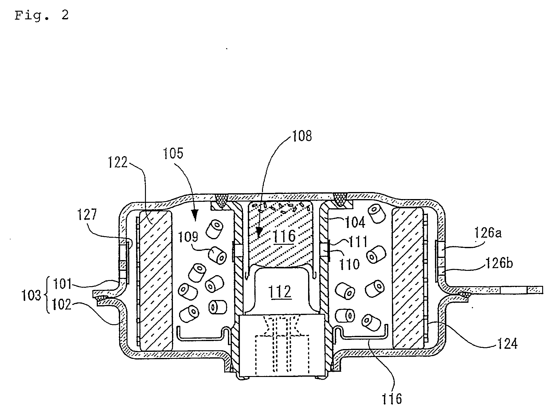
[0087] FIG. 2 is a vertical sectional view of a gas generator for an air bag showing a second embodiment, which has a structure particularly suitable for being arranged on a driver's side. The gas generator shown in this drawing is provided in the housing with one combustion chamber, which is different from the gas generator of the embodiment 1.

[0088] That is, in the gas generator shown in this figure, an inner cylindrical member 104 is disposed in a housing which is formed by joining diffuser shell 101 and a closure shell 102, and an inner-cylindrical member 104, thereby defining an ignition means accommodating chamber 108 in the inside of the inner-cylindrical member 104 and a combustion chamber 105 outside thereof. An ignition means is disposed in the ignition means accommodating chamber 108, and the ignition means comprises an igniter which receives an activating signal to be actuated and a transfer charge 116 which is ignited and burnt by the actuation of the...

embodiment 3

[0096] Embodiment 3

[0097] In the above-described Embodiments 1 and 2, the aspect in which the pressure for opening the gas discharging port is adjusted by the opening area of the gas discharging port is described.

[0098] In the present embodiment, the pressure for opening the gas discharging port is also adjusted by the rupturing pressure of the closing means for the gas discharging port, for example, the seal tape.

[0099] For example, such a constitution can be employed that the opening areas of the gas discharging ports are made equal and the gas discharging port to be opened at the lowest pressure is closed by a seal tape with the lowest rupturing pressure. If the rupturing pressure of the seal tape which closes the gas discharging port is adjusted by its thickness, the rupturing pressure can be lowered by using a thinner seal tape.

[0100] Accordingly, in the gas generator in this aspect, the gas discharging port which is closed by a seal tape having lower rupturing pressure, such a...


PUM


Abstract

The present invention provides a gas generator which exhibits an given operation performance unfailingly. At least two kinds of gas discharging ports to be opened at different pressures are formed, and, among them, the kind of gas discharging ports to be opened at the lowest pressure is arranged to be the gas discharging port nearest to an ignition means, the gas discharging port nearest to a flame-transferring hole, or the gas discharging port nearest to the center of the axial height of a housing.

Description

[0001] The present invention relates to a gas generator for an air bag which can make operation performance optimal, and an air bag apparatus using the same.THE BACKGROUND[0002] An air bag system which is mounted on various kinds of vehicles and the like including automobiles, aims to hold a passenger by means of an air bag (a bag body) rapidly inflated by gas when the vehicle collides at a high speed, so that the passenger is prevented from crashing into a hard portion inside the vehicle such as a steering wheel, a windshield due to an inertia and from getting injured. Generally, this kind of an air bag system comprises a gas generator actuated by a collision of the vehicle to discharge gas, and an air bag to introduce the gas therein to inflate.[0003] The gas generator comprises, in a housing provided with a gas discharging port, an ignition means which receives an activating signal to be actuated and a gas generating means which is to be ignited and burnt by actuation of the igni...

Claims


Application Information

Patent Timeline
IPC IPC(8): B60R21/26B60R21/264
CPCB60R21/2644B60R2021/2648B60R2021/2633
Inventor OHJI, NOBUYUKINAKASHIMA, YOSHIHIRO
Owner DAICEL CHEM IND LTD
Learn More