Self-deploying catheter assembly

a self-deploying, catheter technology, applied in the direction of balloon catheters, catheters, surgery, etc., can solve the problems of increased discomfort, increased catheter diameter, and increased risk of kinks in the lumen of a small diameter

Inactive Publication Date: 2003-09-04
APPL MEDICAL RESOURCES CORP
View PDF1 Cites 65 Cited by
  • Summary
  • Abstract
  • Description
  • Claims
  • Application Information

AI Technical Summary

Problems solved by technology

A larger catheter diameter, however, increases discomfort.
While decreasing the diameter of the inflation lumen may contribute to a slightly smaller overall diameter of a catheter, an inflation lumen with a small diameter is more likely to develop kinks in the passageway, obstructing the flow of fluid necessary to inflate and deflate the balloon.
This greater stack profile: increases discomfort.
Furthermore, particular body cavities can only accommodate a certain length of catheter.
Therefore, limited room is available for the placement of ports on the shaft, which leads to a small ov

Method used


Image

  • Self-deploying catheter assembly
  • Self-deploying catheter assembly
  • Self-deploying catheter assembly

Examples


Embodiment Construction

[0054] The invention and its various embodiments can now be better understood by turning to the following detailed description wherein illustrated embodiments are described. It is to be expressly understood that the illustrated embodiments are set forth as examples and not by way of limitations on the invention as ultimately defined in the claims.

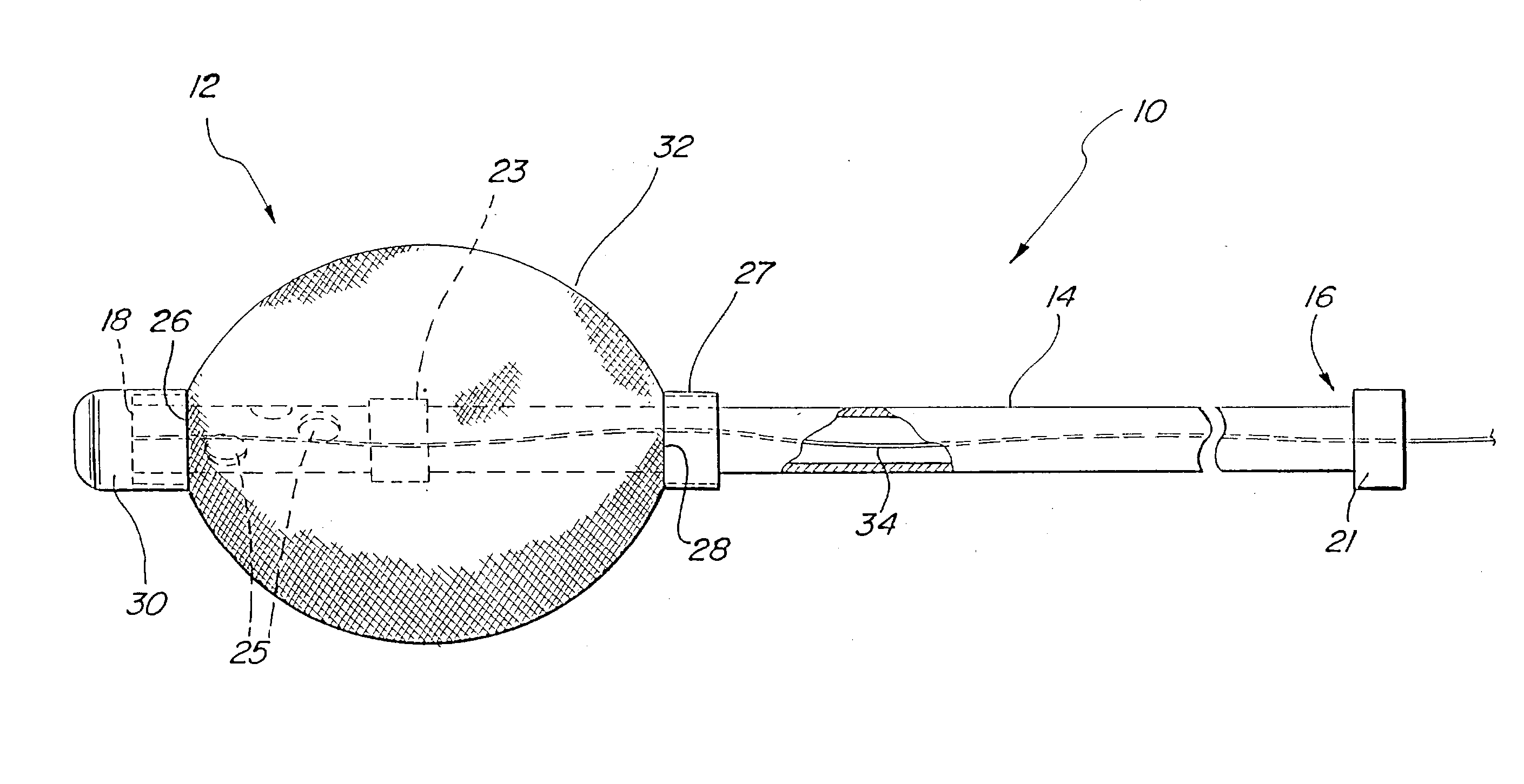
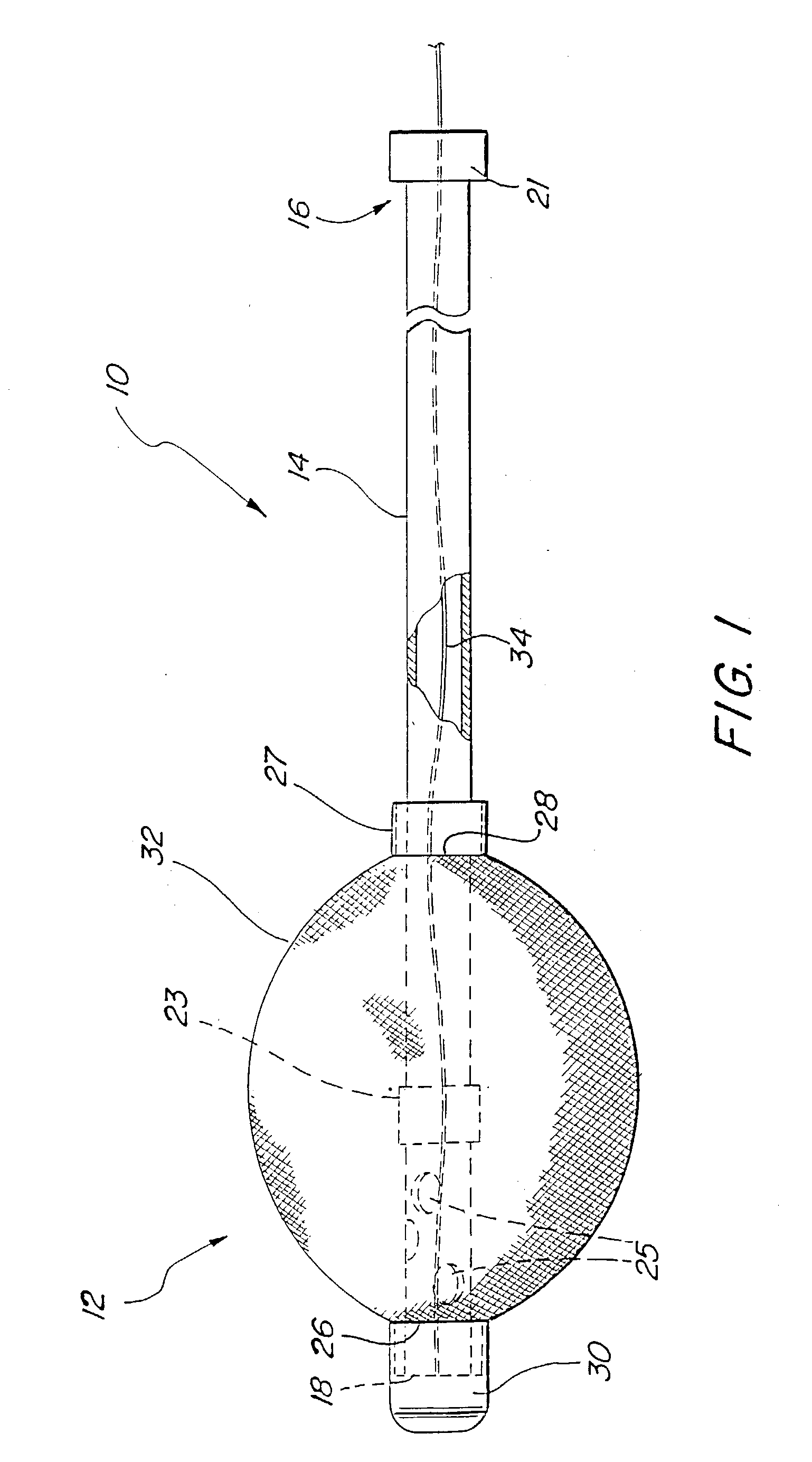
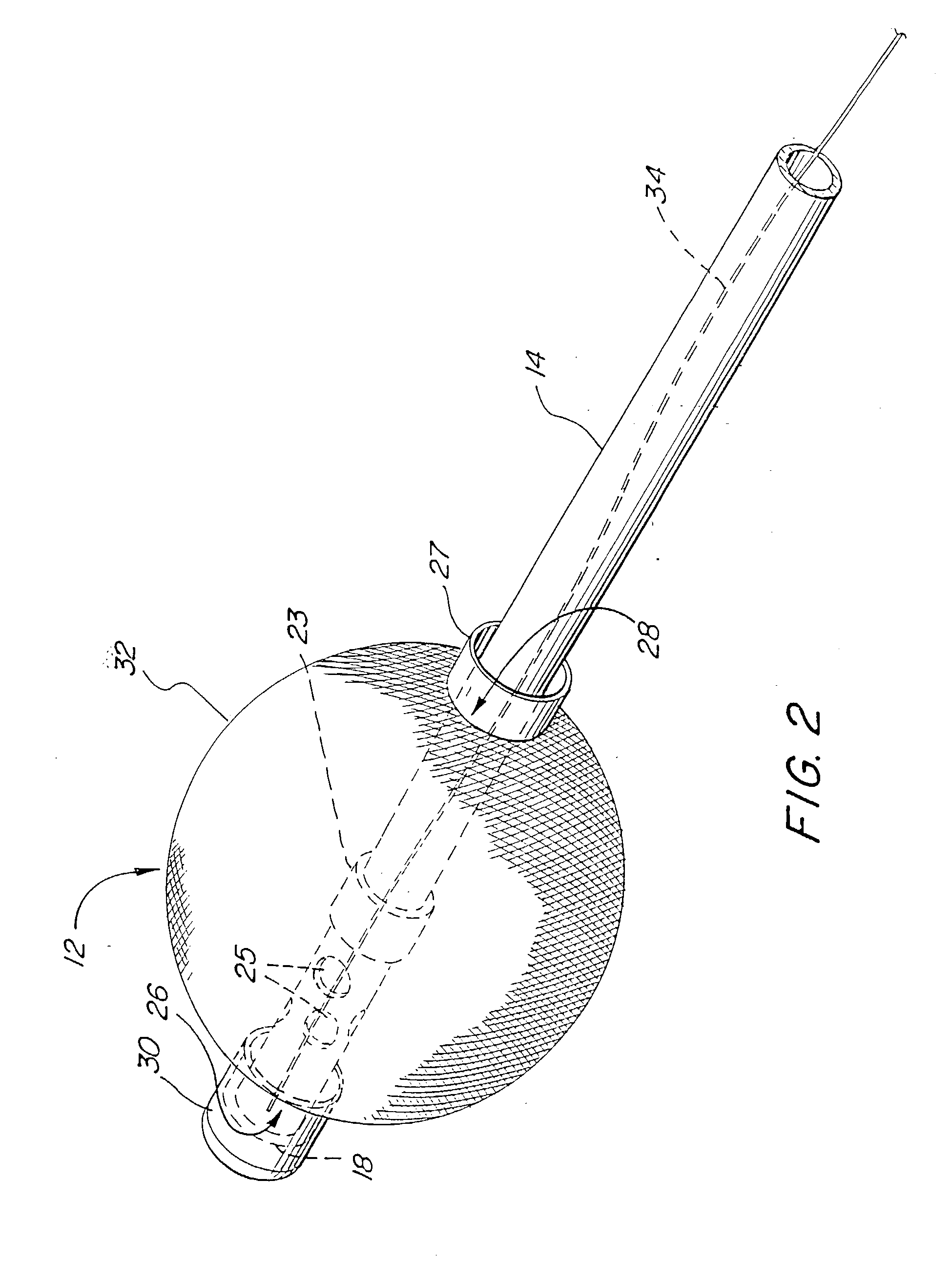
[0055] A first preferred embodiment of a catheter assembly is illustrated in FIG. 1 and designated generally by the reference numeral 10. This catheter assembly, or simply catheter 10, has a self-deploying tip, or anchor assembly 12, which can be advantageous in many catheter configurations. In FIGS. 1 and 2, the catheter 10 is adapted for urinary drainage where the anchor assembly 12 facilitates insertion of the catheter 10, automatic deployment of the tip 12, and simple removal of the catheter 10. Other catheters which can benefit from the serf-deployment properties of the anchor assembly 12 include occlusion catheters, and generally any ...


PUM


Abstract

A catheter having an elongate drainage tube with a proximal end and a distal end, is adapted to extend through a body conduit and into a body cavity. An anchor disposed the distal end of the tube is disposed in the body cavity and is adapted to be moved from an insertion position to a withdrawal position. The anchor in the insertion position has a low profile when the tube is moved distally and in the withdrawal position has a low profile when the tube is moved proximally. The first end of the anchor is attached to the tube, and a tension member is provided to extend distally of the tube to releasably hold the second end of the anchor in a fixed relationship with the tube. In an associated method, this tension member is severed to release the second end of the anchor from the tube and permit withdrawal of the tube and the anchor in a low-profile state.

Description

[0001] This application relates to and claims priority from U.S. Provisional Application Serial No. 60 / 212,912 entitled SELF-DEPLOYABLE DRAINAGE CATHETER filed on Jun. 20, 2000, and U.S. Provisional Application Serial No. 60 / 260,794 entitled ANCHORING ASSEMBLY FOR MEDICAL INSTRUMENT filed on Jan. 9, 2001, and U.S. application Ser. No. 09 / 870,255 filed on May 30, 2001 entitled SELF DEPLOYING CATHETER ASSEMBLY, each of which is incorporated herein by reference[0002] 1. Field of the Invention[0003] The present invention relates generally to medical and surgical devices, and more specifically to catheter assemblies.[0004] 2. Description of Prior Art and Related Information[0005] Catheter assemblies are generally inserted through body conduits to provide access to body cavities so as to enable medical procedures to be performed less invasively. In certain procedures, such as surgery or drainage, it is necessary for the catheter to be temporarily anchored in the body cavity to allow the d...

Claims


Application Information

Patent Timeline
IPC IPC(8): A61F2/958A61M25/00A61M25/04
CPCA61M25/0017A61M25/04A61M2025/1052A61M2025/0213A61M2025/1015A61M25/10
Inventor GONZALES, JOSEPH A.PRAVONG, BOUN
Owner APPL MEDICAL RESOURCES CORP
Why Eureka
Try Eureka