Supercharge Your Innovation With Domain-Expert AI Agents!

Data reception and playback method, data receiving and playback apparatus, and data communication apparatus

Inactive Publication Date: 2003-09-11
PANASONIC CORP
View PDF2 Cites 22 Cited by
  • Summary
  • Abstract
  • Description
  • Claims
  • Application Information

AI Technical Summary

Problems solved by technology

Accordingly, a system clock of a transmitting apparatus is separate from a system clock of a receiving apparatus, which makes it extremely difficult to perfectly synchronize these transmitting and receiving apparatus.
When continuous data is transmitted from a transmitting apparatus to be played in real time in a receiving apparatus, even when the receiving apparatus is equipped with a buffer, underflow or overflow of the continuous data occurs in the receiving apparatus due to the aforementioned difficulty of synchronization.
As a result, problems arise in the receiving apparatus including the loss of continuity of the received data, breaks in the playback sound, noise in the playback sound, and flows in video images.
Moreover, when the environment for transmission is undesirable, it may be necessary to reset a receiving apparatus to its original state while reception of continuous data is in progress, and this results in a long pause in the playback of continuous data.
Still, if there are random delay variations with respect to virtually all packets, it is difficult to achieve accurate synchronization between the system clock of a receiving apparatus and the system clock of a transmitting apparatus.
Moreover, by the above technique, the volume of data that is stored in a receiving buffer fluctuates, when coded data that is output form a coder provided for coding continuous data such as sound and images does not stay at a constant bit rate, or when a packet loss occurs on a transmission channel, which makes it difficult to achieve accurate synchronization between the system clocks of a transmitting apparatus and a receiving apparatus.

Method used


Image

  • Data reception and playback method, data receiving and playback apparatus, and data communication apparatus
  • Data reception and playback method, data receiving and playback apparatus, and data communication apparatus
  • Data reception and playback method, data receiving and playback apparatus, and data communication apparatus

Examples


embodiment 1

[0031] (Embodiment 1)

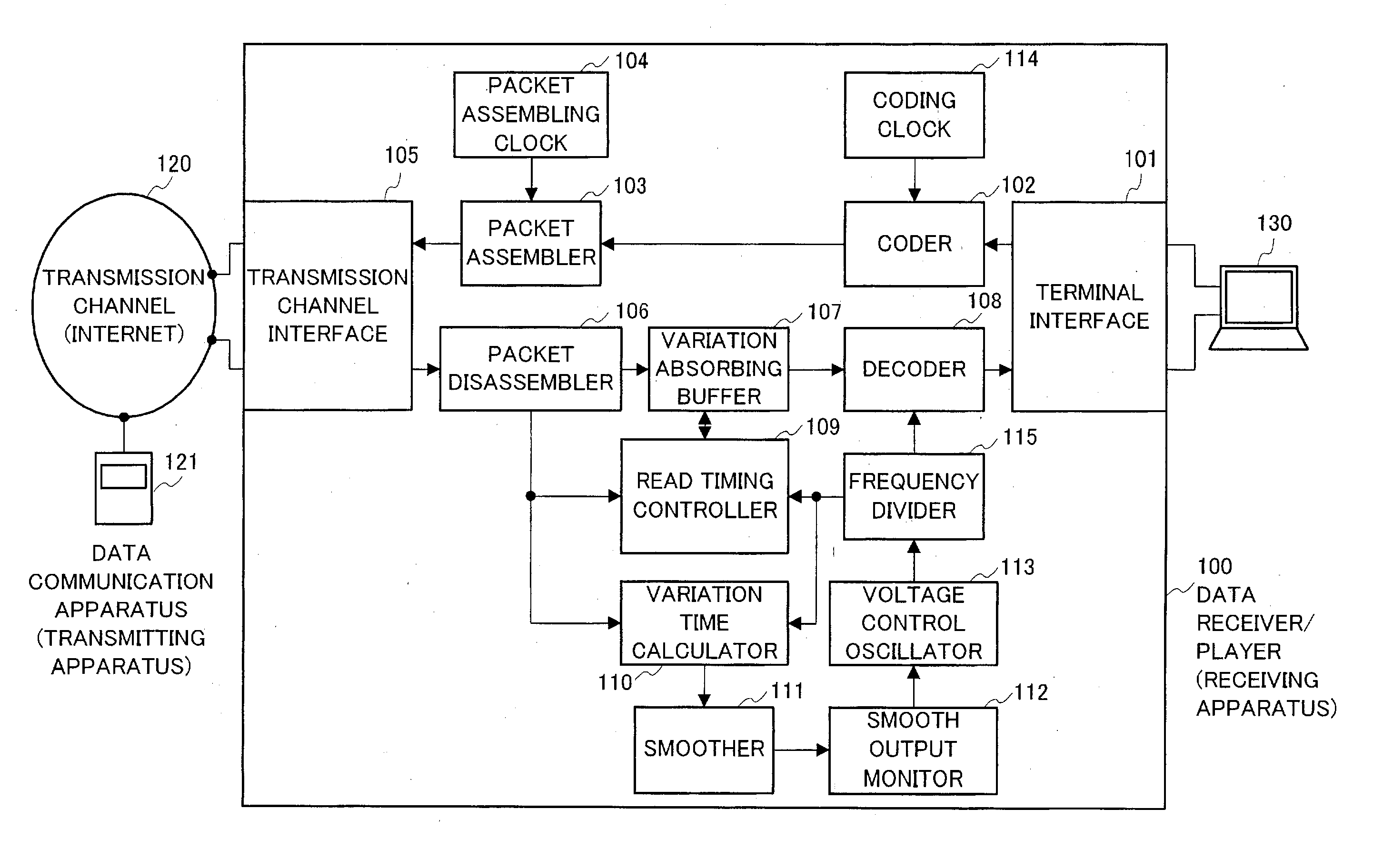
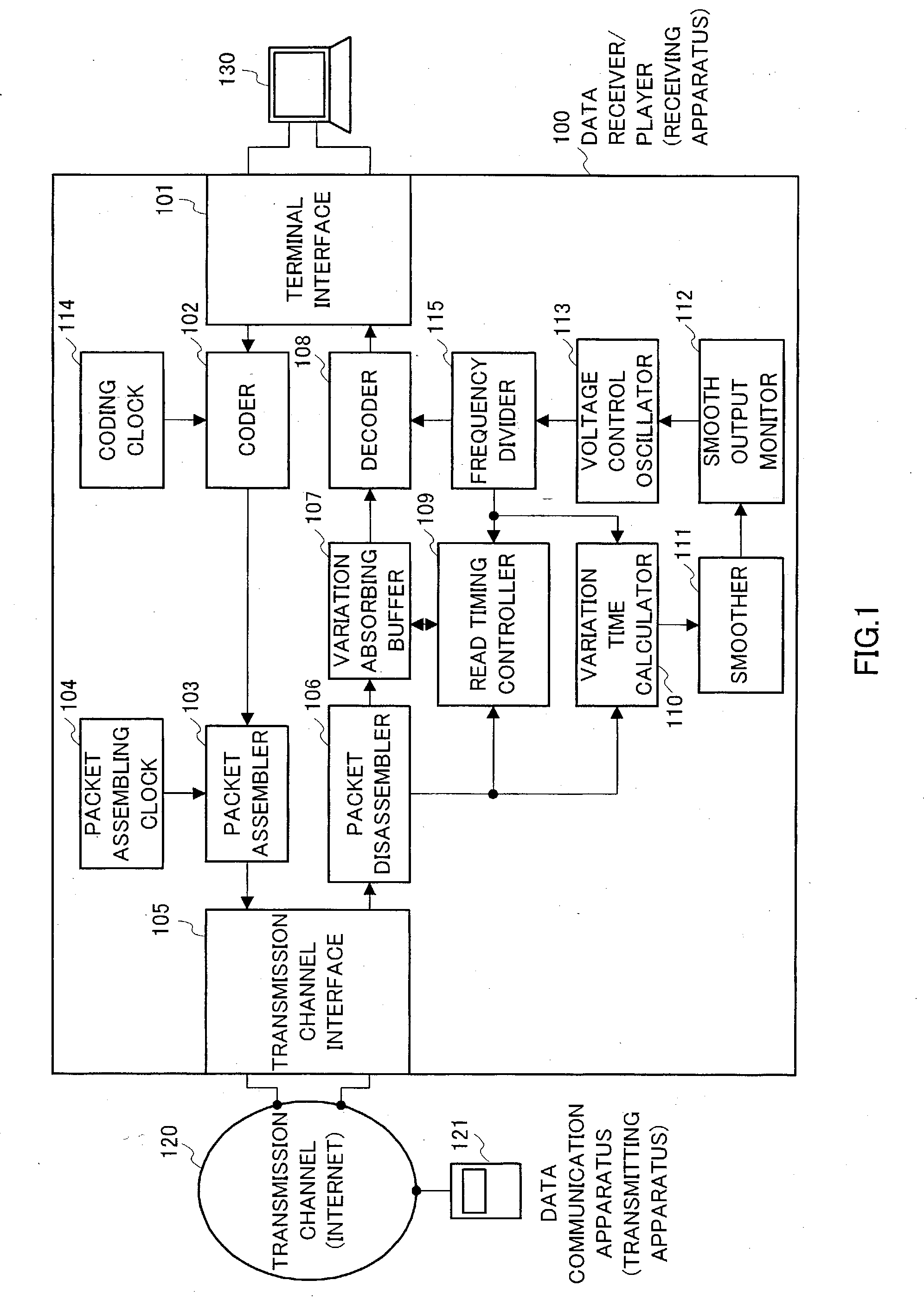
[0032] FIG.1 is a block diagram showing a configuration of a data receiver / player (which becomes data communication apparatus if featuring data transmission function) according to the present mode of embodiment.

[0033] In FIG.1, data receiver / player (hereinafter often referred to as "receiving apparatus") 100 comprises means for receiving a number of packets that are transmitted from a communication partner's communication apparatus (hereinafter often referred to as "transmitting apparatus") and that arrive through transmission channel 120 such as the Internet, for restoring image data or sound data from the packets that are received, and for playing the data by means of connected monitor 130 and the like.

[0034] Referring to the reference numerals of FIG. 1, the components of the data receiver / player of the present invention, and their functions, will be described.

[0035] Terminal interface 101 is an input / output for connecting a microphone, a speaker, a camera, a...

embodiment 2

[0106] (Embodiment 2)

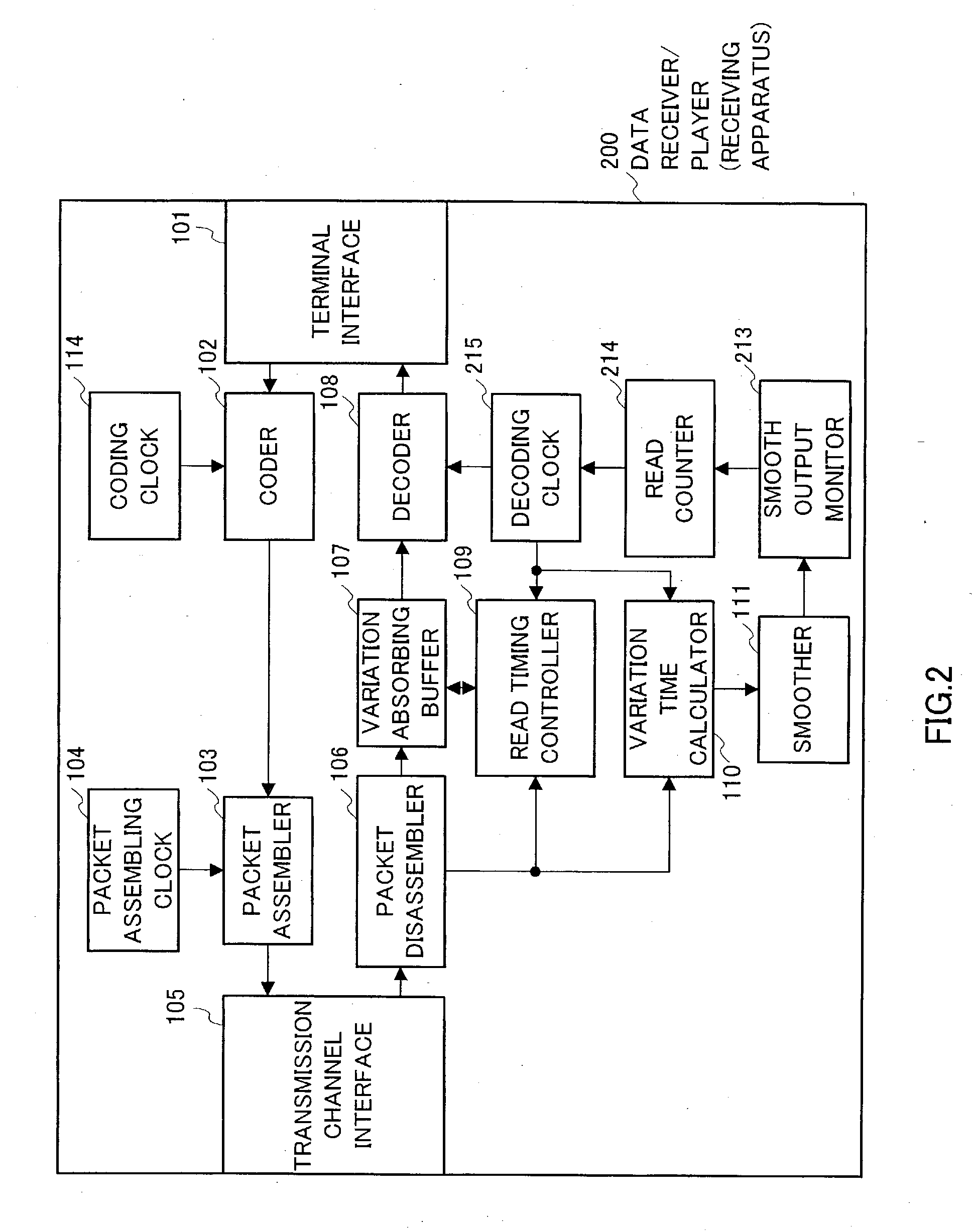
[0107] FIG. 2 is a block diagram showing a configuration of another mode of embodiment of the data receiver / player (data transmitter) of the present invention. Parts in the present embodiment identical to those of the above first embodiment are assigned the same reference numerals without further explanations, and only the parts having different functions than those of the first embodiment will be explained.

[0108] In FIG. 2, read timing controller 109 controls the timing to read out coded data that is stored in variation absorbing buffer 107 based on the time stamp that is temporarily stored in variation absorbing buffer 107 and the counter value on read counter 214.

[0109] Based on the time stamps output from packet disassembler 106 and the counter values on read counter 214, variation time calculator 211 calculates delay variations for each of a number of other packets.

[0110] Smooth output monitor 213 regularly monitors output of smoother 111 and raises or redu...


PUM


Abstract

When packets that are received via a network susceptible to delay variations and data loss are restored into sound and image for a playback where a transmitting apparatus and a receiving apparatus are not synchronized, a data reception and playback method is provided to secure a stable continuous playback by preventing overflow and underflow in a buffer of the receiving apparatus. By the above method, delay variations are calculated variation time calculator 110 in relative to the reference packet based on the information on the time stamps included in the received packets to denote the reception time. Then by smoothing the calculated signals in smoother 111, and then by monitoring, in smooth output monitor 112, difference between the system clock of a transmitting apparatus and the system clock of a receiving apparatus based on the smoothed output signals, and based on this system clock difference the output frequency of voltage control oscillator 113 and the counter value on read counter 214 are corrected.

Description

[0001] 1. Field of the Invention[0002] The present invention relates to methods of data reception and playback, apparatus for data reception and playback, and apparatus for data communication.[0003] 2. Description of Related Art[0004] In recent years, techniques for communicating continuous data that is to be played on audio players and video players through a transmission channel of a network and the like have been in use. In data communications that bypasses a transmission channel, a transmitting apparatus is configured separately from a receiving apparatus. Accordingly, a system clock of a transmitting apparatus is separate from a system clock of a receiving apparatus, which makes it extremely difficult to perfectly synchronize these transmitting and receiving apparatus.[0005] When continuous data is transmitted from a transmitting apparatus to be played in real time in a receiving apparatus, even when the receiving apparatus is equipped with a buffer, underflow or overflow of th...

Claims


Application Information

Patent Timeline
IPC IPC(8): H04J3/06H04L49/9023H04L7/00H04L12/64
CPCH04J3/0632H04L2012/6489H04L12/6418
Inventor FUSE, HIDETOSHI
Owner PANASONIC CORP
Features
  • R&D
  • Intellectual Property
  • Life Sciences
  • Materials
  • Tech Scout
  • Unparalleled Data Quality
  • Higher Quality Content
  • 60% Fewer Hallucinations
Learn More