Electronic control systems and methods

a technology of electronic control system and control system, applied in the direction of pulse manipulation, switch power arrangement, pulse technique, etc., can solve the problems of high average input current, excessive power to be dissipated in the power supply, and often compromised power supply and timing circuit operation

Inactive Publication Date: 2003-09-25
LUTRON TECH CO LLC
View PDF4 Cites 15 Cited by
  • Summary
  • Abstract
  • Description
  • Claims
  • Application Information

AI Technical Summary

Benefits of technology

[0017] According to yet another aspect of the invention, the apparatus employs a system for stabilizing the zero crossing signal received by the electronic control system when the system is operating electronic low voltage transformer connected loads.
[0018] Another embodiment of the present invention is directed toward the protection of controllably conductive devices such as semiconductor devices like MOSFETs and IGBTs used in an electronic control system. Over voltage circuitry senses an over voltage condition across a controllably conductive device which is in the non-conductive state and controls the controllably conductive device to be conductive so as to remove the over voltage condition. Over current circuitry senses when the current through a controllably conductive device has exceeded a predetermined current threshold and controls the controllably conductive device to be non-conductive so as to ensure the safe operating area of the controllably conductive device is not exceeded. The protection circuitry output is desirably configured such that it can bypass and override the normal control path of the controllably conductive device and cause the controllably conductive device to transition rapidly between conduction and non-conduction states.
[0019] According to further aspects of the invention, latching circuitry is employed to keep the results of the protection circuitry in effect even after the fault condition has cleared. Lockout circuitry is used to prevent one protection circuit from tripping after the other protection circuit has already tripped from a particular fault condition.

Problems solved by technology

However, if they are controlled to be conductive, they can only be made non-conductive by allowing the current through them to go to zero.
Due to this characteristic, these types of controllably conductive devices are not used for reverse phase control based control systems where the ability to enable and disable conduction is required.
As such, the operation of the power supply and timing circuit is often compromised in the two wire connection scheme.
Operation outside that time window can cause excessive power to be dissipated in the power supply.
This high average input current presents a significant problem when this supply technology is used with electronic low voltage (ELV) load types on phase control dimmers connected in a two wire mode.
Also, typical prior art power supplies have been relatively inefficient so that they require higher average input currents to supply the power requirements of typical prior art dimmers.
Another disadvantage of prior art power supplies for lighting control devices is that power losses in the power supplies increase with the amount of current required to be delivered by the power supply.
Semiconductor devices, such as MOSFETs, have limits as to how much voltage and current they can withstand without failure.
However, these slow rates of transition during normal operation are too slow for adequate protection of these semiconductor devices.

Method used


Image

  • Electronic control systems and methods
  • Electronic control systems and methods
  • Electronic control systems and methods

Examples


Embodiment Construction

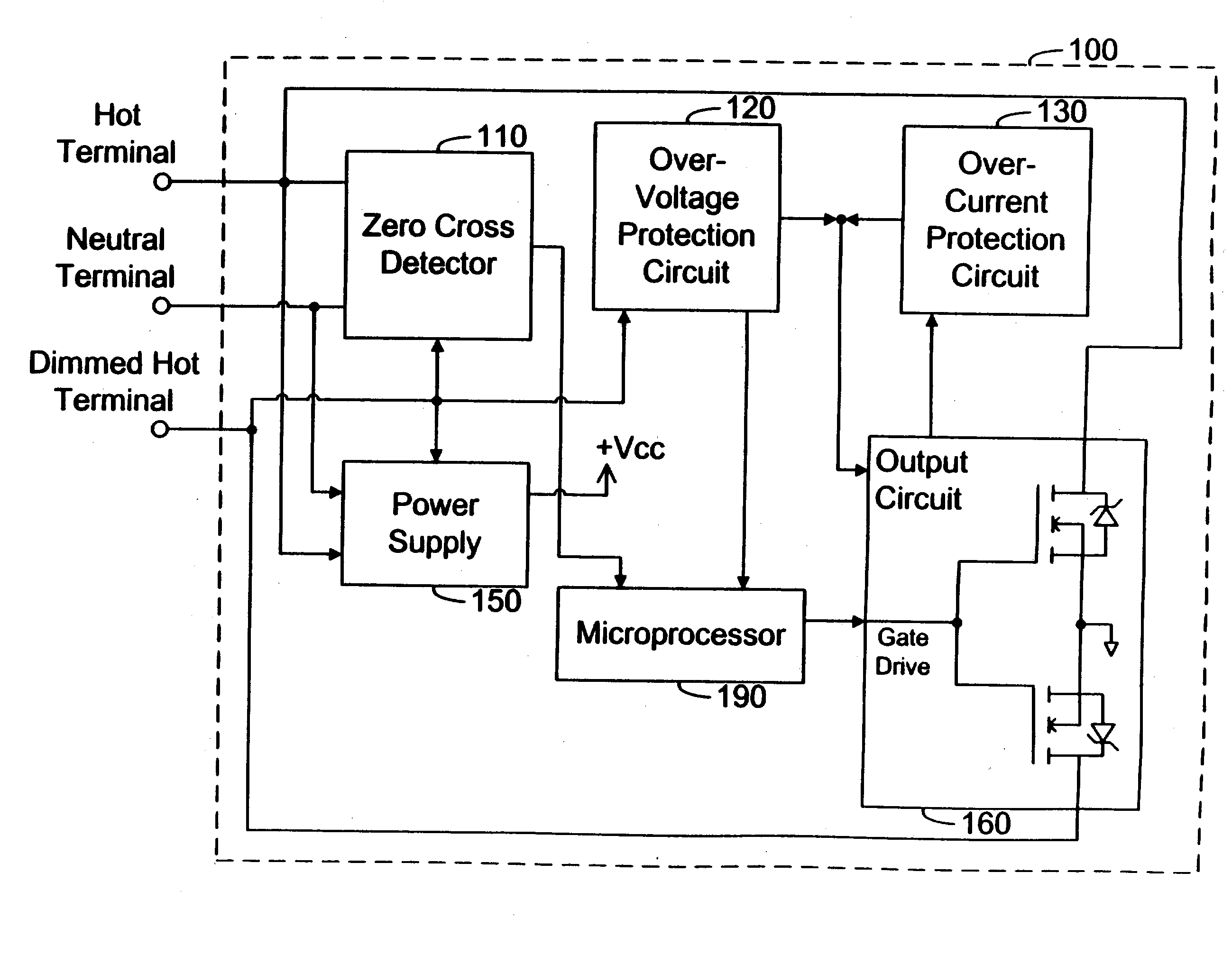
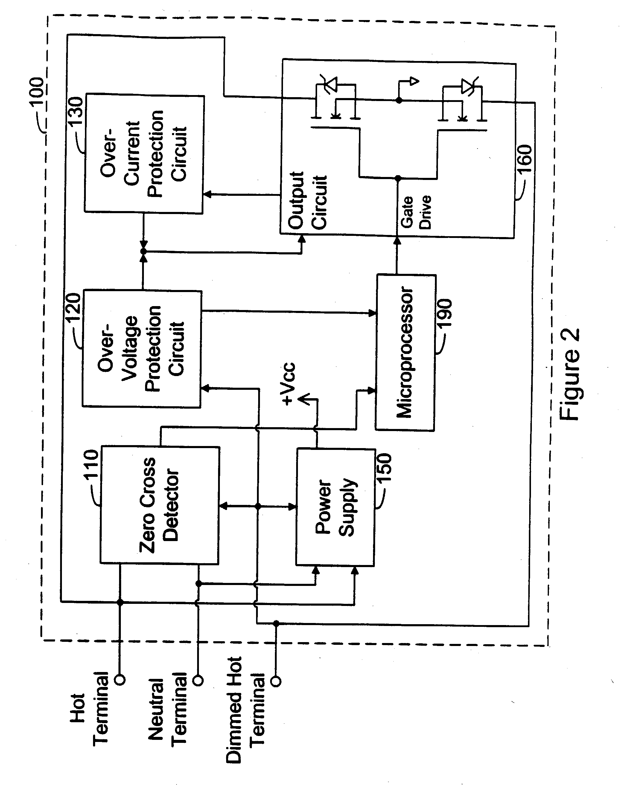
[0036] An embodiment of the present invention is directed to an electronic control system and in particular a lighting controller that can automatically determine whether to operate in two wire mode or three wire mode (i.e., to operate with or without a neutral wire connection). The controller senses whether there is a neutral wire connection to the electronic control system and adjusts its operation accordingly. The electronic control system automatically selects and continuously monitors the connection scheme. An embodiment is directed toward an electronic control system such as a lighting controller or dimmer; however, the invention has broader application in other electronic controls.

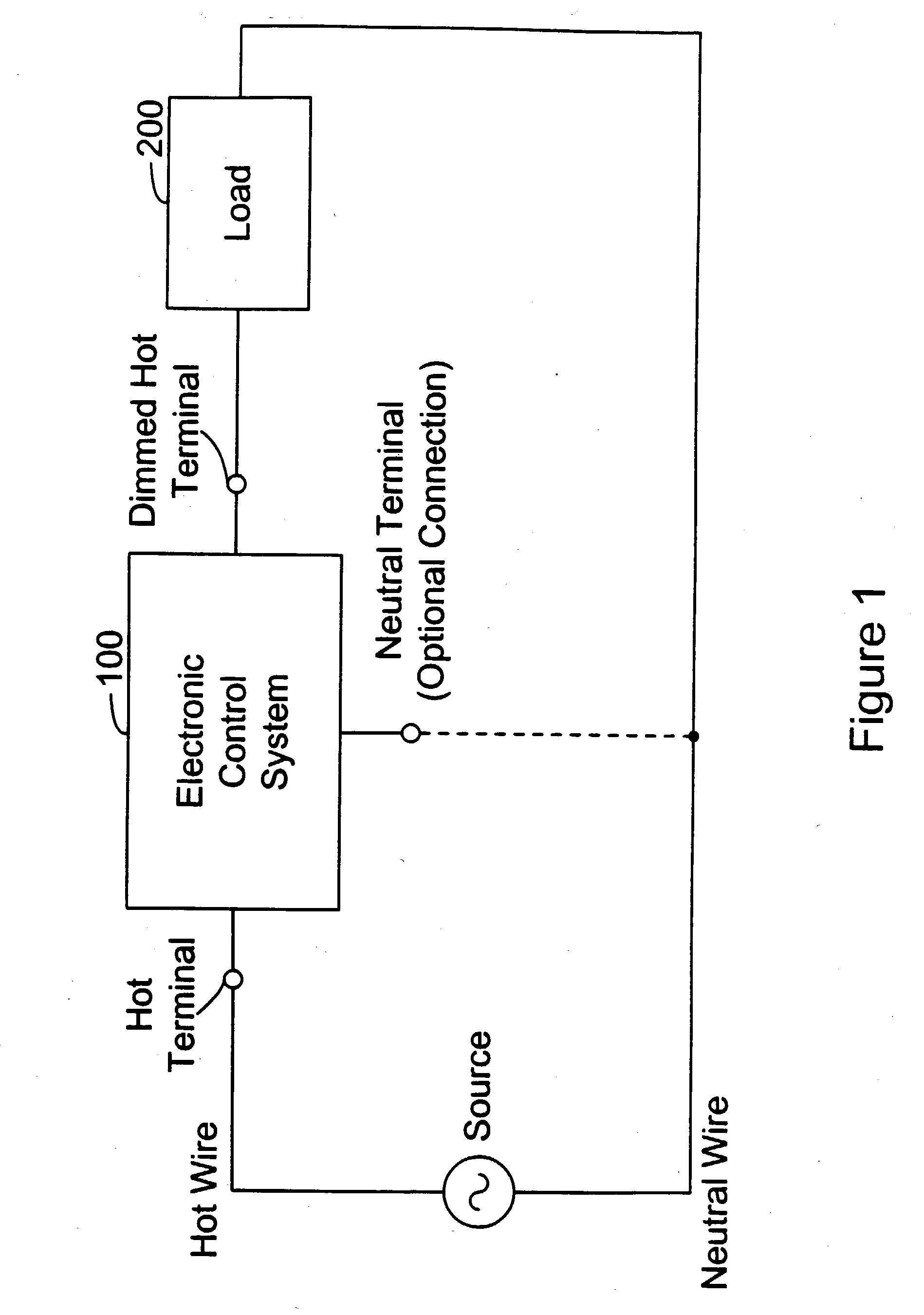
[0037] FIG. 1 is a high level block diagram of an exemplary system in accordance with the present invention. An electronic control system 100, also referred to herein as a lighting controller or a dimmer, is preferably connected between an input source, such as an AC line voltage, and a first termin...


PUM


Abstract

An apparatus in an electronic control system allows two or three wire operation. A power supply can supply power to the enclosed circuitry in both two and three wire installations. Two separate zero cross detectors are used such that timing information can be collected in both two and three wire installations. Both zero cross detectors are monitored and are used to automatically configure the electronic control. Over voltage circuitry senses an over voltage condition across a MOSFET which is in the off state and turns the MOSFET on so that it desirably will not reach the avalanche region. Over current circuitry senses when the current through the MOSFETs has exceeded a predetermined current threshold and then turns the MOSFETs off so they do not exceed the MOSFETs' safe operating area (SOA) curve. Latching circuitry is employed to keep the protection circuitry in effect even after a fault condition has cleared. Lockout circuitry is used to prevent one protection circuit from tripping after the other circuit has already tripped from a fault condition. The protection circuitry output is desirably configured such that it can bypass and override the normal turn on and turn off impedance and act virtually directly on the gates of the MOSFETs. Preferably, the system has a high efficiency switching type power supply in parallel with a low frequency controllably conductive device.

Description

[0001] This application claims the benefit of U.S. Provisional Application No. 60 / 303,508, filed Jul. 6, 2001, the entire disclosure of which is hereby incorporated by reference.[0002] The present invention relates in general to electronic control circuits and systems, and more particularly, to lighting control circuits and systems.[0003] There are many applications where it is desirable to control the amount of average electrical power delivered to a load. One example of such an application is the use of a lighting dimmer to control the output of a lamp. A dimmer typically functions by controlling the conduction of current through the load. A controllably conductive device is synchronized to the AC line voltage and is controlled to conduct for a predetermined interval in each half cycle of the AC line voltage. That is, the load only receives power (is on) for a portion of the AC line voltage half cycle. The longer the conduction time, the more power delivered to the load. By the sa...

Claims


Application Information

Patent Timeline
Patent Type & Authority Applications(United States)
IPC IPC(8): H02M7/538H03K5/1536H05B37/02H03K17/082H03K17/13H03K17/687H05B39/04H05B39/08
CPCH02M1/32H02M5/293H02M7/538H02M2001/0012H03K3/00Y02B20/148H03K17/0822H03K17/6874H03K2017/0806H05B39/048H05B39/08H03K17/00H02M1/0012H02H7/12Y02B20/00
Inventor BLACK, RICHARD L.CHRISTENSEN, GRAHAMJOHNSON, BENJAMIN AARONLEICHLITER, SHAWN L.NEWMAN, ROBERT C. JR.THOMPSON, STEPHEN SPENCERWU, CHENMING
Owner LUTRON TECH CO LLC
Why Eureka
Try Eureka