Chiller compressor circuit containing turning vanes

Inactive Publication Date: 2003-10-16
CARRIER CORP
View PDF0 Cites 24 Cited by
  • Summary
  • Abstract
  • Description
  • Claims
  • Application Information

AI Technical Summary

Benefits of technology

0006] The gaseous refrigerant flow, although having a short flow path, must make at least one 90.degree. turn which produces flow losses. The flow into a condenser of the shell and tube type is typically perpendicular to the tube direction and the tubes are simply supported. The refrigerant condenses on the outside of tubes carrying water which takes the heat out of the refrigerant gas. Therefore, it is common practice to place a plate between the discharge flow and the condenser tubes to prevent direct impingement of the discharge gas on the tubes which can cause the tubes to vibrate and f

Problems solved by technology

The gaseous refrigerant flow, although having a short flow path,

Method used


Image

  • Chiller compressor circuit containing turning vanes
  • Chiller compressor circuit containing turning vanes
  • Chiller compressor circuit containing turning vanes

Examples


Embodiment Construction

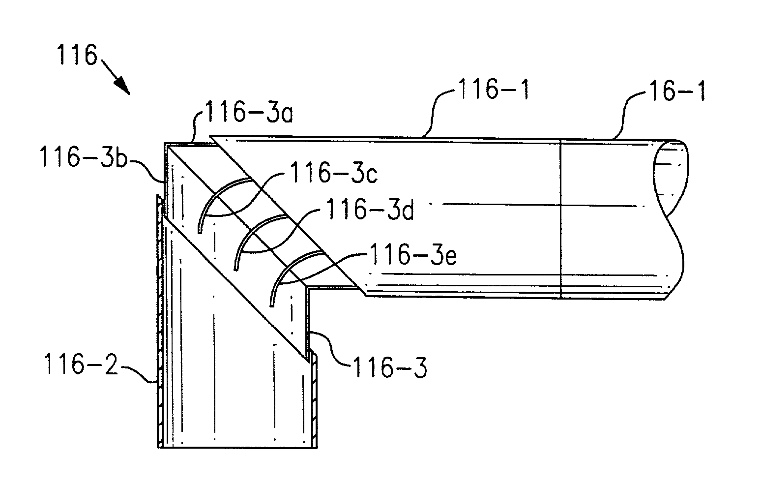
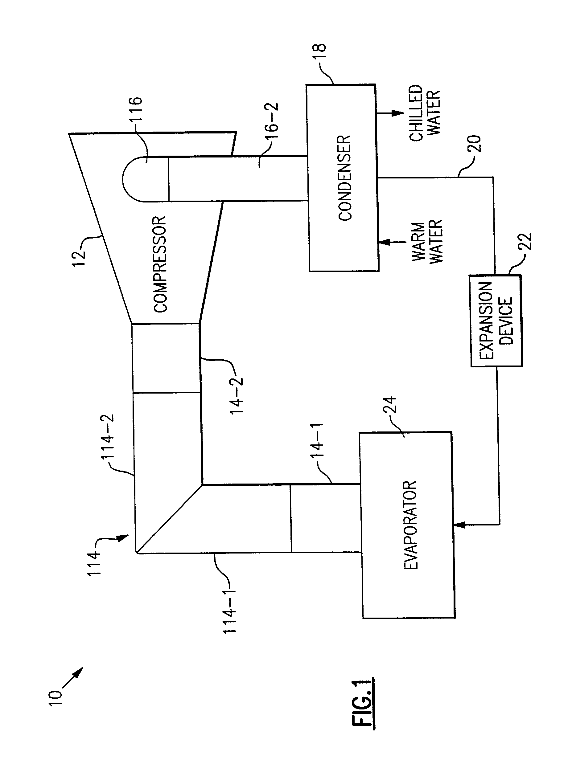
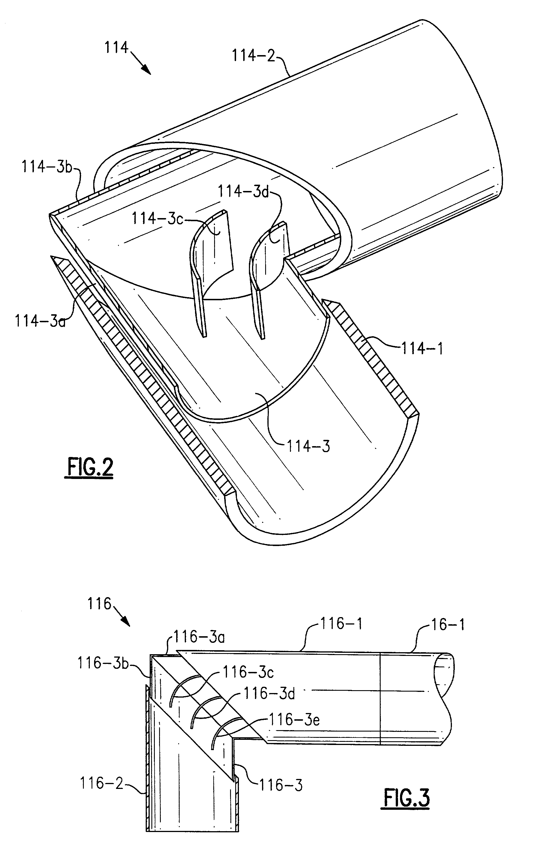
[0017] In FIG. 1, the numeral 10 generally designates a centrifugal chiller refrigeration or air conditioning system. Compressor 12 is a motor driven centrifugal compressor and, using the example given above, it is capable of delivering 300 tons (3,600,000 Btu / hr) of cooling. The suction line extends from evaporator 24 to compressor 12 and is made up of legs 14-1 and 14-2 totaling three feet in length of eight inch diameter pipe with 90.degree. elbow 114 located therebetween. Elbow 114 is illustrated as a mitered elbow made up of legs 114-1 and 114-2 which may be legs 14-1 and 14-2, respectively. Referring specifically to FIG. 2, it will be noted that elbow 114 contains a mitered insert 114-3 having legs 114-3a and 114-3b which are snugly received in legs 114-1 and 114-2, respectively, with legs 114-3a and 114-3b being illustrated as only partially inserted into legs 114-1 and 114-2, respectively. When fully assembled, legs 114-1 and 114-2 will be suitably secured together, as by we...


PUM


Abstract

Turning vanes are located in the suction and discharge line elbows of a refrigerant circuit and at the entrance to the condenser.

Description

BACKGROUND OF THE INVENTION[0001] In a central air conditioning system providing cooling, there are at least two fluid circuits. One circuit is the closed circuit in which the refrigerant is compressed, condensed and expanded. The second circuit is where conditioned air is supplied to the zone(s) and subsequently withdrawn to be re-cooled. A third fluid circuit would exist where chilled water is circulated to fan coil units to provide cooling to the air passing through / over the coils and the water is subsequently returned to the chiller of the air conditioning system to be re-cooled. The air conditioning system and fan coil units are very compact relative to the volumes for which they provide cooling.[0002] Conditioned air is delivered by fans or blowers into ductwork and passes via terminals into zones / rooms. The conditioned air will typically be dehumidified when the system is in the cooling mode. The air supplied to a zone cannot be too cool or at too rapid a velocity as to cause...

Claims


Application Information

Patent Timeline
IPC IPC(8): F16L43/00F16L55/027
CPCF16L55/027F16L43/001
Inventor MACBAIN, SCOTT M.
Owner CARRIER CORP
Why Eureka
Try Eureka