RF MEMS switch loop 180 degree phase bit radiator circuit

a phase bit radiator and switch loop technology, applied in waveguides, resonant antennas, waveguide types, etc., can solve the problems of consuming dc power, affecting the operation of the device, so as to achieve the effect of reducing the cost of the devi

Inactive Publication Date: 2003-10-16
RAYTHEON CO
View PDF0 Cites 27 Cited by
  • Summary
  • Abstract
  • Description
  • Claims
  • Application Information

AI Technical Summary

Problems solved by technology

These devices are relatively heavy, consume relatively large amounts of DC power and are relatively expensive.
The implementation of PIN diodes and FET switches into RF phase shifter circuits is further complicated by the need of additional DC bias circuitry along the RF path.
The DC biasing circuit needed by PIN diodes and FET switches limits the phase shifter frequency performance and increase RF losses.

Method used


Image

  • RF MEMS switch loop 180 degree phase bit radiator circuit
  • RF MEMS switch loop 180 degree phase bit radiator circuit
  • RF MEMS switch loop 180 degree phase bit radiator circuit

Examples


Embodiment Construction

[0020] The following exemplary embodiments employ MEM metal-metal contact switches. U.S. Pat. No. 6,046,659, the entire contents of which are incorporated herein by this reference, describes a MEM switch suitable for the purpose.

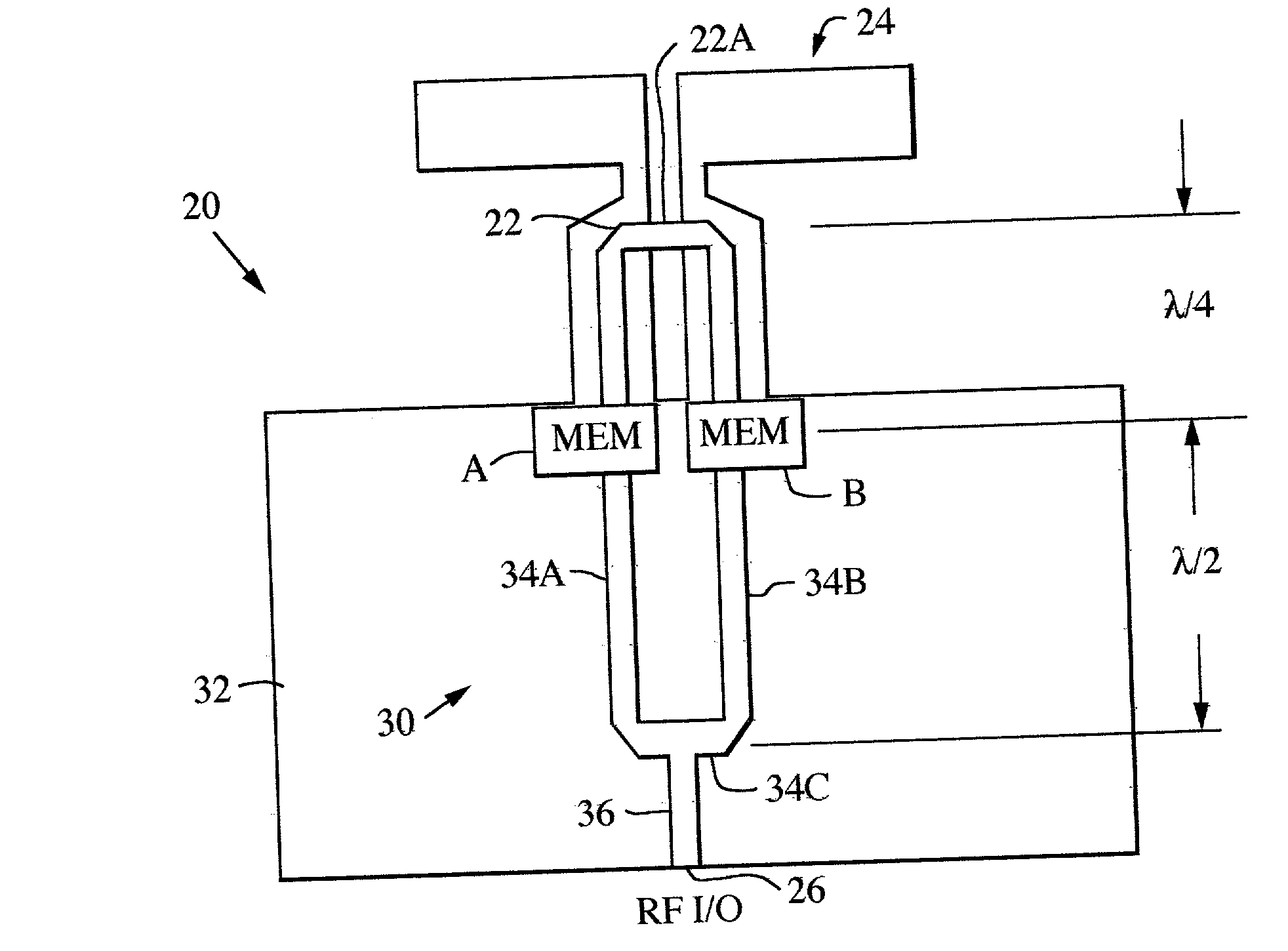
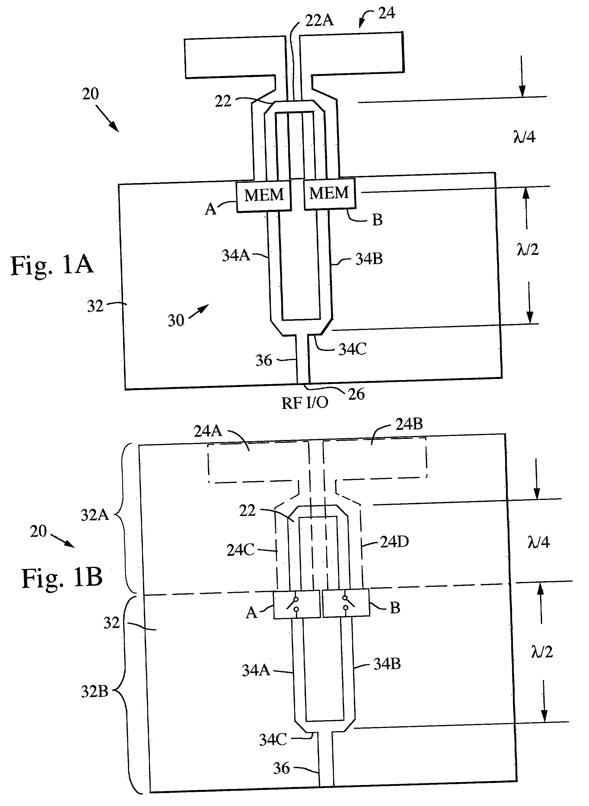
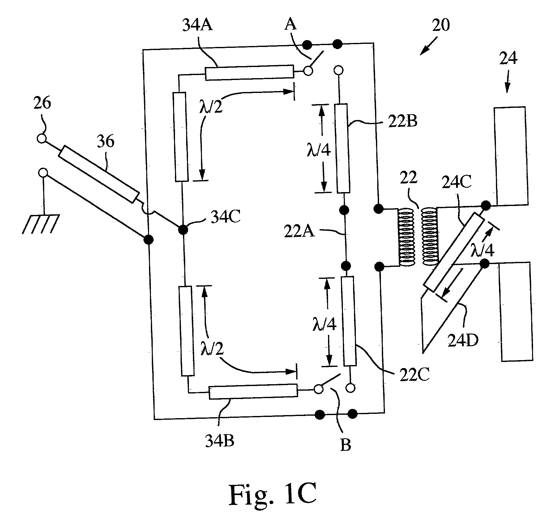
[0021] A new class of switch loop 180.degree. phase bit radiator circuit configurations is described. In one exemplary embodiment, illustrated in FIGS. 1A-5, a switch loop phase bit radiator circuit 20 generates 180.degree. phase shift by rerouting the RF signal around a loop transition or balun 22 by means of two single pole single throw switches (SPST) A and B. The circuit 20 includes a radiating element 24, shown here as a dipole. The circuit RF I / O port 26 is positioned in a microstrip transmission line circuit 30, comprising a dielectric substrate 32 on which microstrip conductor lines are defined, in a manner well known to those skilled in the art. The conductor pattern defines the loop legs 34A and 34B, which join together at junction 34C to conductor...


PUM


Abstract

A switched loop RF radiator circuit, comprising a radiator element, a circuit RF input/output (I/O) port, and a balun coupled between the radiator element and the I/O port. The balun includes a 180° switched loop circuit having two transmission line legs coupled to a balun transition to provide a selectable 180° phase shift, and a microelectromechanically machined (MEM) switch cirtuit. Many radiator circuits can be deployed in an electronically scanned antenna array.

Description

BACKGROUND OF THE DISCLOSURE[0002] Exemplary applications for this invention include space-based radar systems, situational awareness radars, and weather radars. Space based radar systems will use electronically scan antennas (ESAs) including hundreds of thousands of radiating elements. For each radiating element, there is a phase shifter, e.g. 3 to 5 bits, that, collectively in an array, control the direction of the antenna beam and its sidelobe properties. For ESAs using hundreds of thousands of phase shifters, these circuits must be low cost, be extremely light weight (including package and installation), consume little if no DC power and have low RF losses (say, less than 1 dB). For space sensor applications (radar and communications) these requirements exceed what is provided by known state of the art devices.[0003] Current state of the art devices used for RF phase shifter applications include ferrites, PIN diodes and FET switch devices. These devices are relatively heavy, con...

Claims


Application Information

Patent Timeline
Patent Type & Authority Applications(United States)
IPC IPC(8): H01P1/12H01P5/10H01Q3/38
CPCH01P1/127H01Q3/38H01P5/10
Inventor QUAN, CLIFTONPIERCE, BRIAN M.
Owner RAYTHEON CO
Why Eureka
Try Eureka