Lightweight part, as well as a process and device for its production

Inactive Publication Date: 2003-10-23
HUTTE KLEIN REICHENBACH
View PDF15 Cites 9 Cited by
  • Summary
  • Abstract
  • Description
  • Claims
  • Application Information

AI Technical Summary

Benefits of technology

[0012] The advantages achieved with the invention are essentially to be seen in that the lightweight part is produced from two parts whose surfaces are joined together. In this way, the parts can be formed easily. Moreover, the core part can be formed independently of the outer wall body.
[0033] If, as is per se known, a gas inlet system is used which has nozzle parts projecting into the melt material and is arranged at the bottom of the wall of the melt vessel and beneath the pouring or filling piece, the metal foam can be produced with largely the same bubble size. In this way, the supporting effect of the core surface layer can be improved.

Problems solved by technology

Unfortunately, such complicated internal shapes of cast parts typically require the sand cores used in their production.
Such a process is very labor intensive.
However, there are a number of disadvantages with this method.
These relate to limitations relating to shape and thicker wall areas.
However, the molded body surface, which is formed by the wall areas of the respective foam bubbles adjacent to the mold wall, is thin.
However, foam bodies produced in this way have the disadvantages that due to the thin foam bubble wall, and in particular with large individual bubbles, their surface can only be loaded to a limited extent.
Thus, it is obviously not favorable to pour these molded bodies into a melt with a different composition.
This is because this leads to uncontrollable penetrations and to the collapse of foam bubble walls or in particular of larger bubbles at the surface of the body.
As a result, the weight of the part is also affected in an unforeseeable manner.
It should be noted, however, that if the temperature of the casting mold it too high, for example, in the area of the solidus temperature of the alloy, this can lead to the liquid metal emerging from the gaps and air exits and / or to the collapse of the foam bubbles at these points.
It can also have a disadvantageous effect on at least the surface quality of the core part, and in particular, on its loading capacity.

Method used


Image

  • Lightweight part, as well as a process and device for its production
  • Lightweight part, as well as a process and device for its production
  • Lightweight part, as well as a process and device for its production

Examples


Embodiment Construction

[0062] The particulars shown herein are by way of example and for purposes of illustrative discussion of the embodiments of the present invention only and are presented in the cause of providing what is believed to be the most useful and readily understood description of the principles and conceptual aspects of the present invention. In this regard, no attempt is made to show structural details of the present invention in more detail than is necessary for the fundamental understanding of the present invention, the description taken with the drawings making apparent to those skilled in the art how the several forms of the present invention may be embodied in practice.

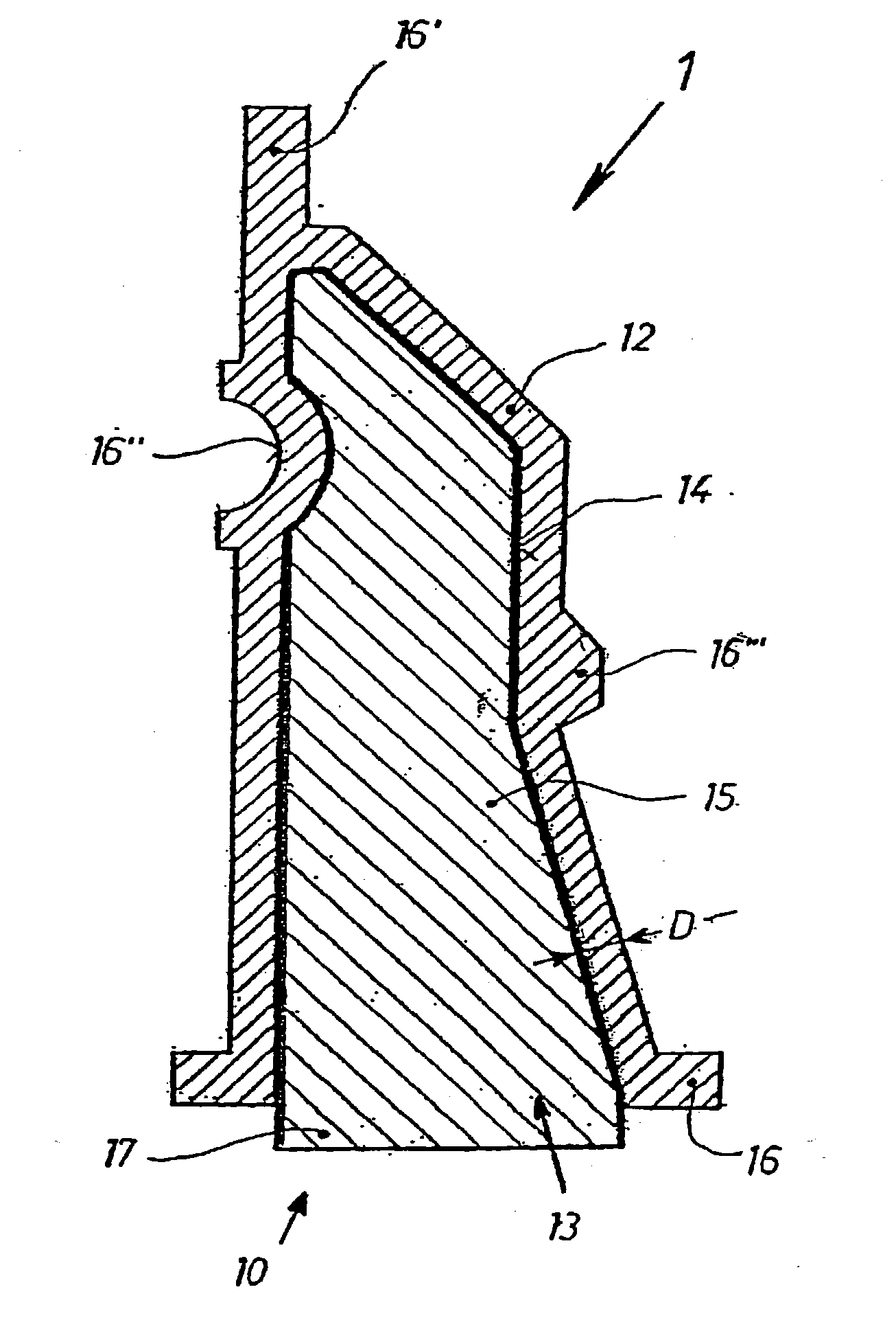
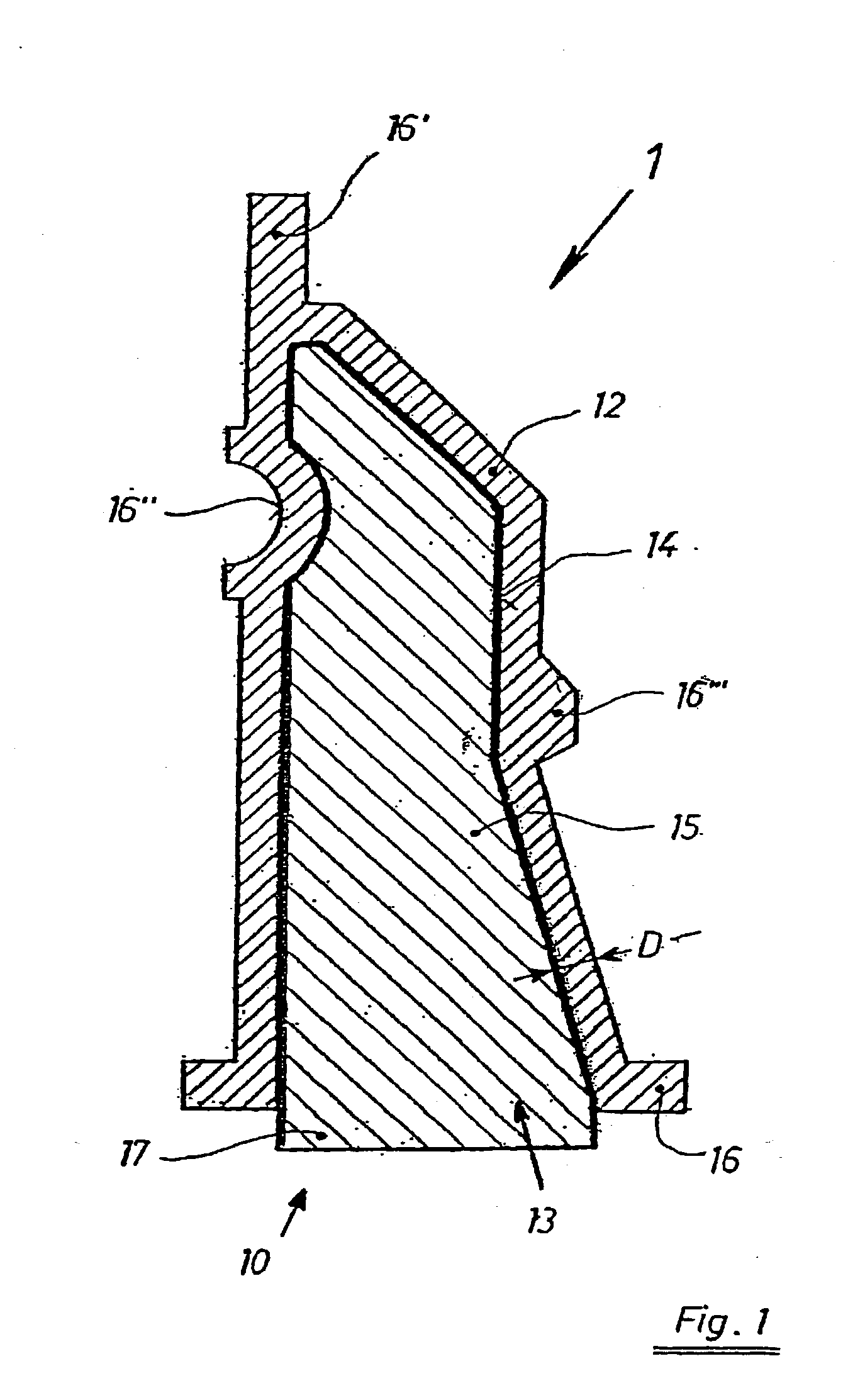
[0063] With reference to FIG. 1, a lightweight part 1 has a core part 10 and an outer wall body 12 that has a thickness D. This thickness D can vary or be constant as desired. A dense closed core surface layer 14 is arranged adjacent the outer wall body 12 and between the core part 10 and the body 12. The core part 10 ha...


PUM

PropertyMeasurementUnit
Thicknessaaaaaaaaaa
Thicknessaaaaaaaaaa
Thicknessaaaaaaaaaa

Abstract

A lightweight part and process and device of making the same, the lightweight part including an inner core including a metal foam. A dense core surface layer is metallically joined to the inner core. An outer wall includes an essentially pore-free cast metal layer that is at least one of positively engaged with the dense core surface layer and surrounding the inner core, and metallically joined to the dense core surface layer and surrounding the inner core. The process includes creating a core part by forming the dense core surface layer, forming the inner core of a metal foam, and metallically joining together the inner core and the dense core surface layer. The process further includes creating a finished part by positioning the core part in a casting mold, feeding a melt material into the casting mold, and allowing the melt material to solidify so as to form the outer wall. This abstract is neither intended to define the invention disclosed in this specification nor intended to limit the scope of the invention in any way.

Description

[0001] The present application claims priority under 35 U.S.C. .sctn.119 of Austrian Patent Application No. A 610 / 2002, filed on Apr. 19, 2002, the disclosure of which is expressly incorporated by reference herein in its entirety.[0002] 1. Field of the Invention[0003] The invention relates to a lightweight part. The invention also relates to a process and a device for producing the lightweight part.[0004] 2. Discussion of Background Information[0005] As a rule, lightweight parts are used, for example, in various supporting or holding functions. They are also used in construction or machine components. They are made to have mechanical and, if necessary, vibration-damping properties, and are also required to simultaneously have low weight. More precisely, such lightweight parts should feature a mass distribution (or material distribution) such that when the part is loaded (or subjected to loading), specific mechanical material stresses whose level is as equal as possible, prevail in a...

Claims


Application Information

Patent Timeline
IPC IPC(8): B22D19/02B22D17/00B22D19/08B22D25/00B22F7/00C22C1/08
CPCB22D19/08B22D25/005B22F7/006C22C1/08Y10T428/12486C22C2001/086C22C2204/00Y10T428/12479C22C2001/083C22C1/083C22C1/086
Inventor DOBESBERGER, FRANZFLANKL, HERBERTLEITLMEIER, DIETMARBIRGMANN, ALOIS
Owner HUTTE KLEIN REICHENBACH
Why Eureka
Try Eureka