Corrections for pulse reverberations and phasefront aberrations in ultrasound imaging

a phasefront aberration and ultrasound imaging technology, applied in the field of corrections for pulse reverberation and phasefront aberration in ultrasound imaging, can solve the problems of destroying the focusing of the beam mainlobe, reducing the focusing of the beam sidelobe, and reducing the focusing of the beam

Inactive Publication Date: 2003-10-23
ANGELSEN BJ O SLASHED RN A J +1
View PDF4 Cites 19 Cited by
  • Summary
  • Abstract
  • Description
  • Claims
  • Application Information

AI Technical Summary

Problems solved by technology

However, with large variations of the acoustic properties in complex structures of tissue, the following effects will degrade the images:
ii) Variations of the acoustic velocity within the complex tissue structures produce forward propagation aberrations of the acoustic wavefront, destroying the focusing of the beam mainlobe and increasing the beam sidelobes.
The reduced focusing of the beam main lobe reduces the spatial resolution in the ultrasound imaging system.
Increasing the transmitted pulse power will hence not improve the power ratio of the signal to the noise of this type, contrary to what is found with electronic receiver noise.
It is therefore a challenge to reduce the image degrading effect of pulse reverberations and phase front aberrations in the body wall in many applications of medical ultrasound imaging.
The body wall often contains mixtures of such tissues, and body wall phase aberrations and pulse reverberations are therefore a major cause of image degradation found with non-invasive ultrasound imaging in many patients.
Especially, due to the large reflection coefficient of the transducer array itself, pulse reverberations that involves at least one reflection from the transducer array often produce disturbing noise in the image.
However, it is generally a problem to estimate the correction filters from the signals that is back scattered in typical imaging situations, as for example described in [2].
One major problem for such filter estimation is the noise produced by pulse reverberations in the body wall, especially the strong pulse reverberations that includes reflections from the ultrasound transducer itself.

Method used


Image

  • Corrections for pulse reverberations and phasefront aberrations in ultrasound imaging
  • Corrections for pulse reverberations and phasefront aberrations in ultrasound imaging
  • Corrections for pulse reverberations and phasefront aberrations in ultrasound imaging

Examples


Embodiment Construction

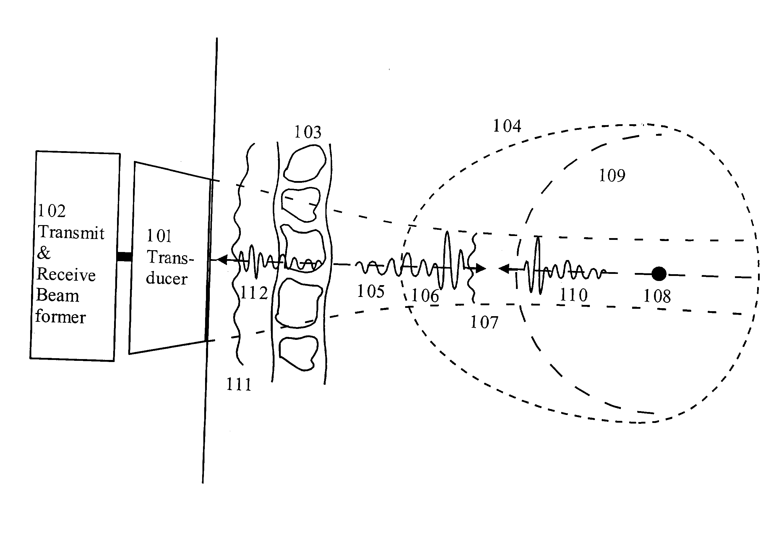
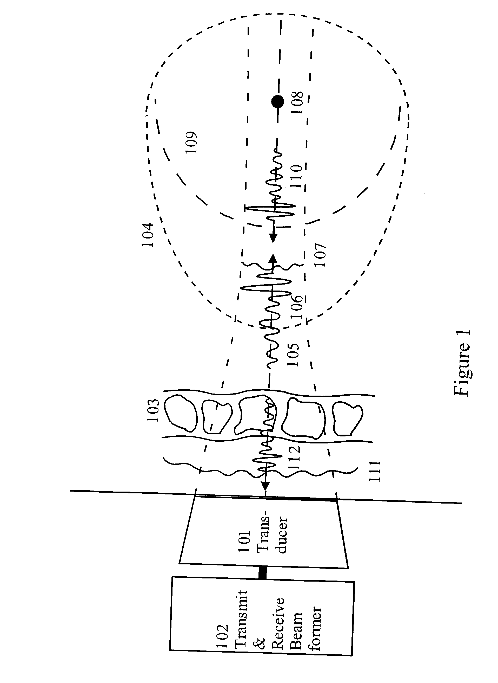
[0044] FIG. 1 shows a typical measurement situation where an ultrasound transducer array (101) driven by a transmit beam former (102), transmits a pulsed and focused ultrasound beam through the body wall (103) towards an object (104) to be imaged. The body wall is a heterogeneous mixture of fat, muscles, and connective tissue with differences in acoustic velocity and characteristic impedance. Multiple reflections within the body wall and between structures in the body wall and the transducer, produces a reverberation tail (105) to the transmitted pulse (106) as it passes the wall. Similarly, the variations in the acoustic velocity produce aberrations of the phasefront (107) as the pulse passes the wall.

[0045] At reflection of the pulse from a point scatterer (108) within the object, a wave with spherical wave front (109) is reflected, with a second order temporal differentiation so that the essence of the band limited temporal variation of the pulse with reverberation tail is preser...


PUM


Abstract

A method of correcting for pulse reverberations in ultrasound imaging using two-dimensional transducer arrays, and uses such reduction in element signals and beam signal before estimation of corrections for phase front aberrations of the ultrasound wave. The pulse reverberation is estimated by two transmit events, where the second event is determined by measurement and processing on measurement on echoes of the first event. In a second embodiment of the invention, the reverberation is estimated by a single transmit event, using two receive beams and processing on these. In a third embodiment of the invention the reverberation from very strong scatterers is reduced by adjustment of the active transmit aperture.

Description

1. PRIORITY CLAIM[0001] Priority is claimed for this invention and application, corresponding application having been filed in US on Apr. 5, 2002, No. 60 / 370,417.[0002] 1. Field of the Invention[0003] The present invention is directed to methods for estimating corrections for the image degradation produced in medical ultrasound images by pulse reverberations and phasefront aberrations of the ultrasound wave in the tissue. The method hence has applications to all situations were ultrasound imaging is used in medicine, and also other similar situations of ultrasound imaging.[0004] 2. Description of the Related Art[0005] Spatial variations in the acoustic properties of tissues (mass density and compressibility) are the basis for ultrasound back scatter imaging of soft tissues. However, with large variations of the acoustic properties in complex structures of tissue, the following effects will degrade the images:[0006] i) Interfaces between materials with large differences in acoustic p...

Claims


Application Information

Patent Timeline
Patent Type & Authority Applications(United States)
IPC IPC(8): G01S7/52G01S15/89
CPCG01S7/52049G01S15/8927G01S15/8925G01S7/52095
Inventor ANGELSEN, BJORN A.J.JOHANSEN, TONNI F.
Owner ANGELSEN BJ O SLASHED RN A J
Why Eureka
Try Eureka