Method for making hollow glass optical waveguide

a hollow glass and optical waveguide technology, applied in glass making apparatus, other domestic objects, manufacturing tools, etc., can solve the problems of limited wavelength span, difficult to make a waveguide with a very small inner diameter, and high manufacturing cos

Inactive Publication Date: 2003-11-06
HEWLETT PACKARD DEV CO LP
View PDF16 Cites 15 Cited by
  • Summary
  • Abstract
  • Description
  • Claims
  • Application Information

AI Technical Summary

Problems solved by technology

Therefore, the manufacturing cost tends to be high due to the elaborate processes and the lengths of produced fibers are usually limited to 2-3 m. In these prior methods, dielectric and metal films are coated on the inner surface of tubing by flowing liquid or gaseous precursors.
Therefore, it is difficult to make a waveguide with a very small inner diameter which is highly flexible.
However, the wavelength span is limited due to the material properties, although the target wavelength can be shifted by mixing some different glasses.
Moreover, material absorption which slightly exists in those glasses lowers the reflective coefficient at the inner wall, and thus, the transmission loss of the fabricated waveguide is usually high even at the target wavelength.

Method used


Image

  • Method for making hollow glass optical waveguide
  • Method for making hollow glass optical waveguide
  • Method for making hollow glass optical waveguide

Examples


Embodiment Construction

[0015] Preferred embodiments of the present invention will hereinafter be described with reference to the accompanying drawings.

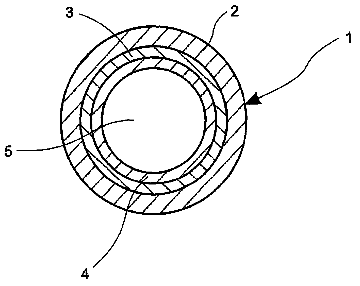
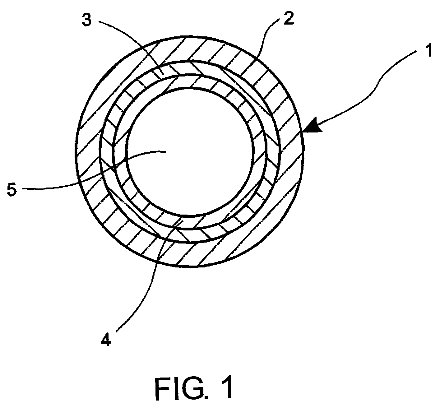
[0016] FIG. 1 is a cross sectional view of an embodiment of the hollow waveguide according to the present invention. As shown in the figure, the hollow waveguide 1 is composed of a glass layer 2, a metal layer 3 on the outside of the glass tube, and a protective layer 4.

[0017] In the present invention a glass tube is employed as a preform. Absorption coefficient of the glass should be small at the target wavelength region. Silica glass is a preferable material because of the high transparency in ultraviolet, visible, and infrared regions. Some glasses which have lower glass transition temperature, such as Pyrex glasses and sodium glasses, are preferred when low-cost production is important. For mid- to far-infrared regions, some special glasses such as chalcogenides are preferred due to the high transparency at the longer wavelength than 3 .mu.m.

[0018] A gl...


PUM

PropertyMeasurementUnit
lengthsaaaaaaaaaa
inner diameteraaaaaaaaaa
thicknessaaaaaaaaaa

Abstract

A method for making optical hollow-glass waveguide. The present invention comprises a glass drawing and following metal coating processes. The waveguide produced by this method provides low transmission loss at target wavelengths in ultraviolet, visible, and infrared regions when the wall thickness of the glass tube is well controlled so as to fit to the designed parameter.

Description

[0001] 1. Field of the Art[0002] This invention relates to optical waveguides, and more particularly to a flexible hollow waveguide for transmitting ultraviolet, visible, and infrared light.[0003] 2. Prior Art[0004] Hollow fibers are promising, flexible delivery media of high-powered infrared lasers used in medical and industrial fields. Some hollow fibers are already employed in laser systems due to the flexibility, ruggedness, high power capability, and low losses. These fibers are usually fabricated by depositing a metal and dielectric films on the inner surface of pre-drawn glass or plastic tubing. See U.S. Pat. No. 5,440,664, issued to Harrington, and U.S. Pat. No. 4,930,863, issued to Croitoru. Therefore, the manufacturing cost tends to be high due to the elaborate processes and the lengths of produced fibers are usually limited to 2-3 m. In these prior methods, dielectric and metal films are coated on the inner surface of tubing by flowing liquid or gaseous precursors. Theref...

Claims


Application Information

Patent Timeline
Patent Type & Authority Applications(United States)
IPC IPC(8): C03B37/026C03B37/027C03C17/00C03C17/38C03C17/40
CPCC03B37/026C03B37/027C03C17/40C03C17/004C03C17/38C03B2203/16
Inventor MATSUURA, YUJIMIYAGI, MITSUNOBUKATAGIRI, TAKASHI
Owner HEWLETT PACKARD DEV CO LP
Why Eureka
Try Eureka