Electromagnetic induction casting apparatus

a technology of induction casting and ingots, which is applied in the direction of manufacturing tools, electric/magnetic/electromagnetic heating, crystal growth process, etc., can solve the problem of excessive cooling of ingots immediately after cooling, and achieve the effect of simplifying restoring work, reducing the cost of exchange, and simplifying the exchange work

Inactive Publication Date: 2003-11-06
SUMITOMO MITSUBISHI SILICON CORP
View PDF1 Cites 28 Cited by
  • Summary
  • Abstract
  • Description
  • Claims
  • Application Information

AI Technical Summary

Benefits of technology

0055] When the bottomless crucible 2 requires restoring deformation which has been accumulated for long term use, the assembling type bottomless crucible permits disassembling either of the water-cooled section 2a or the non-water-cooled section 2b, thereby simplifying a restoring work. Similarly, the assembling type bottomless crucible simplifies an exchange work and lowers a cost required for exchange. An effect to prevent the water-cooled section 2a from being deformed outside can be obtained by configuring the bottomless crucible 2 to have a structure in which a convex portion formed on an inner circumferential portion of a bottom surface of the water-cooled section 2a is fitted in a concave portion formed in an inner circumferential portion of a top surface of the non-water-cooled section 2b as shown in FIG. 5. By the way, the water-cooled section 2a may be loaded from the melt 11 formed therein and has a relatively high possibility of being deformed outward.

Problems solved by technology

For the lower section of the bottomless crucible which faces a skin of a solidified ingot, on the other hand, a water-cooling structure will cool the lower section excessively, thereby causing excessive cooling of the ingot immediately after solidification.

Method used


Image

  • Electromagnetic induction casting apparatus
  • Electromagnetic induction casting apparatus
  • Electromagnetic induction casting apparatus

Examples


Embodiment Construction

[0056] Now, examples of the present invention will be compared with a conventional example to clarify effects of the present invention.

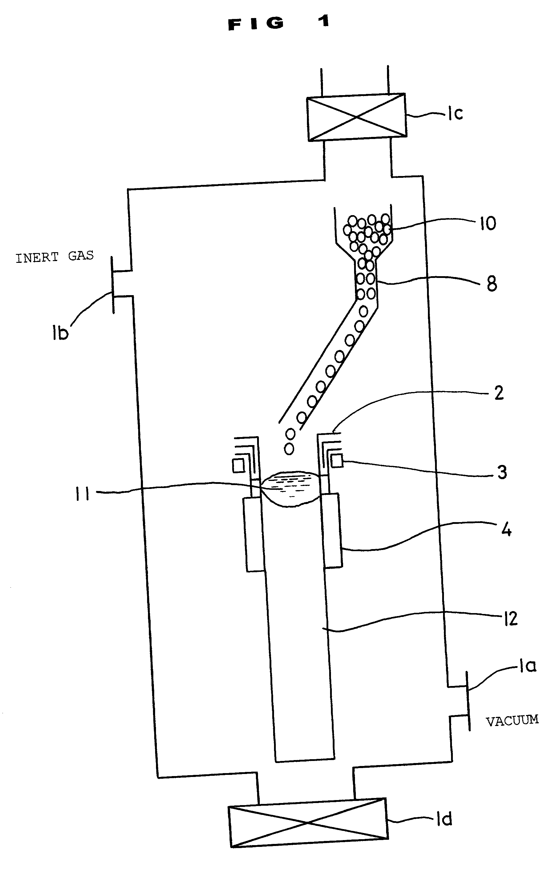
[0057] As Example 1, a unidirectionally solidified polysilicon ingot to be used in a solar cell was manufactured using the electromagnetic induction casting apparatus according to the first embodiment shown in FIGS. 1 through 3. A casting speed was 2 mm / min.

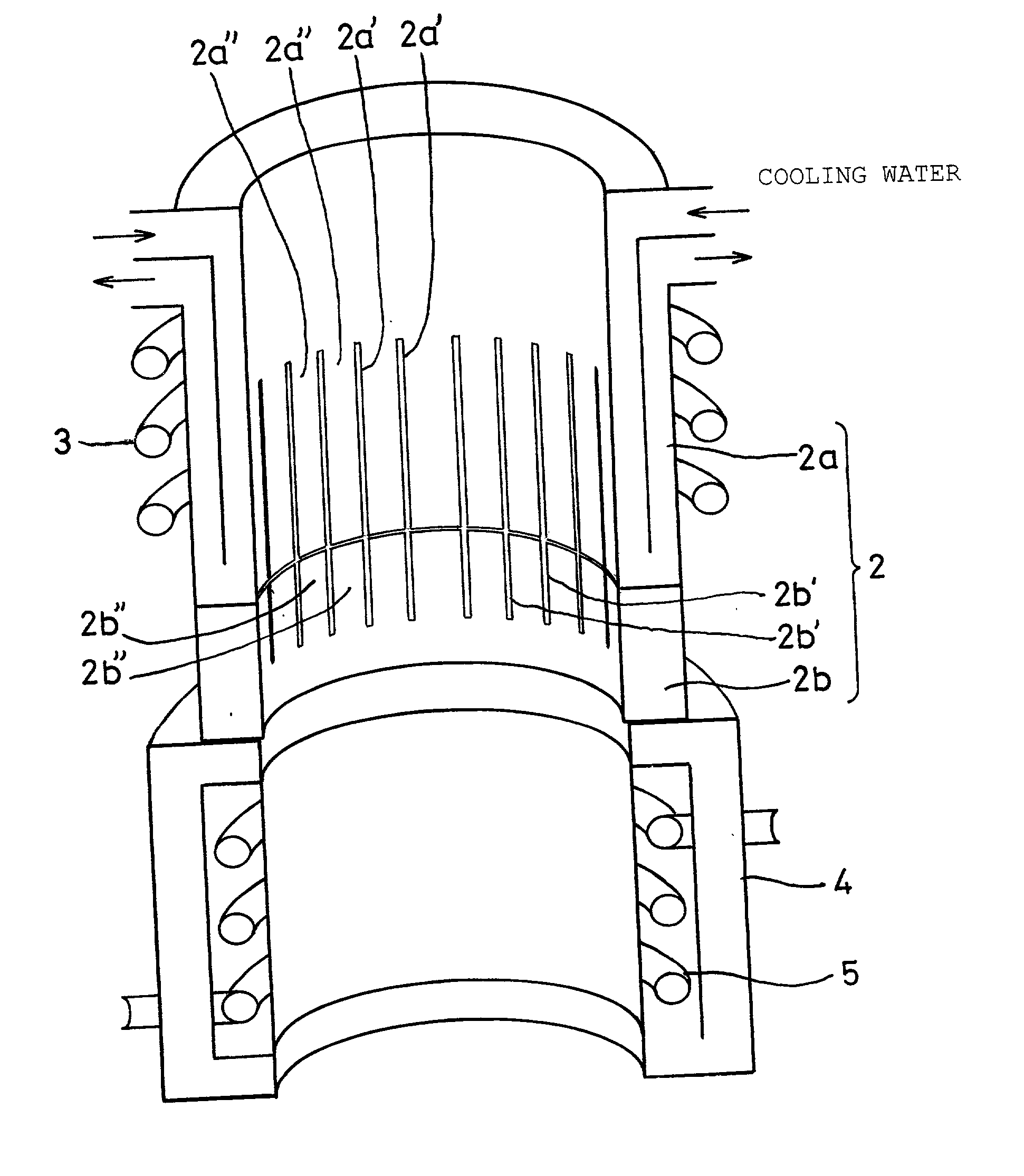
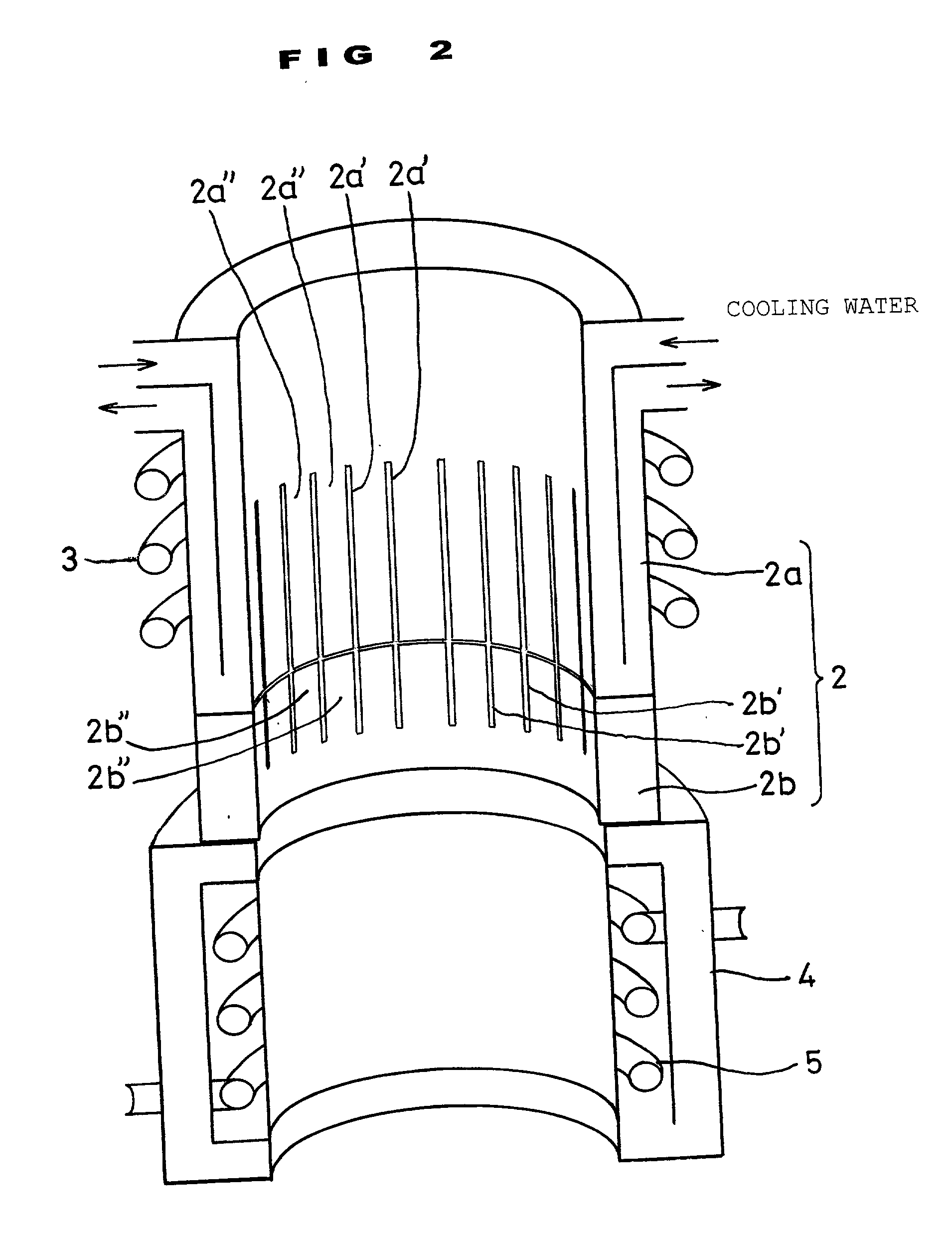
[0058] A bottomless crucible used had an inside diameter of 300 mm, a total height of 500 mm, a total slit length of 350 mm and slits in a number of 22. A water-cooled section as an upper portion of the crucible was made of copper and had a height of 390 mm. On the other hand, a non-water-cooled section as a lower portion of the crucible was made of molybdenum and had a height of 110 mm. Furthermore, the water-cooled section had a slit length of 250 mm and the non-water-cooled section had a slit length of 100 mm. A lowermost portion 10 mm in height of the non-water-cooled section had no slit to as...


PUM

PropertyMeasurementUnit
melting pointaaaaaaaaaa
temperatureaaaaaaaaaa

Abstract

To restrict to a low level a temperature gradient of an ingot immediately after solidification in a bottomless crucible in a electromagnetic induction casting method using an electrically conductive bottomless crucible. An upper section and a lower section of an electrically conductive bottomless crucible to be disposed inside an induction coil are configured as a water-cooled section and a non-water-cooled section. Both the water-cooled section and the non-water-cooled section are divided by vertical slits into a plurality of portions in a circumferential direction. Rapid cooling with water in the lower section of the crucible is restricted.

Description

[0001] 1. Field of the Invention[0002] The present invention relates to an electromagnetic induction casting apparatus which is used, for example, to manufacture a silicon ingot for a solar cell.[0003] 2. Description of the Prior Art[0004] As one of methods for manufacturing unidirectionally solidified ingots of silicon used in solar cells, an electromagnetic induction casting method disclosed in Japanese Patent Laid-Open Nos. 2-30698, 4-338195 are known, for example. A typical electromagnetic induction casting method uses an induction coil 3, an electrically conductive bottomless crucible 2 which is disposed inside the induction coil 3 and a heat insulating furnace 4 which is disposed under the bottomless crucible 2 as shown in FIG. 8.[0005] The electrically conductive bottomless crucible 2 has a structure in which at least a vertical portion is divided by vertical slits 2', 2', . . . into a plurality of vertically elongated sections 2", 2", . . . in a circumferential direction, co...

Claims


Application Information

Patent Timeline
Patent Type & Authority Applications(United States)
IPC IPC(8): C30B15/08B22D11/115B22D23/06C22B9/00
CPCB22D11/115C22B9/003B22D23/06B22D11/001B22D11/041B22D11/1213B22D27/003Y02P10/25
Inventor KIMURA, NARITOSHISASATANI, KENICHIKANEKO, KYOJIRO
Owner SUMITOMO MITSUBISHI SILICON CORP
Why Eureka
Try Eureka