
Method and apparatus for software-assisted thermal management for electronic systems

a technology of electronic system and software, applied in the direction of liquid/fluent solid measurement, instruments, sustainable buildings, etc., can solve the problems of power dissipation, major limitation of high-performance microprocessor design, and inability to solve in lower-end systems,

Inactive Publication Date: 2003-11-20
FOCUS GLOBAL SOLUTIONS LLC
View PDF7 Cites 66 Cited by
  • Summary
  • Abstract
  • Description
  • Claims
  • Application Information

AI Technical Summary

Problems solved by technology

Already, power dissipation presents a major limitation on the design of high-performance microprocessors.
While power dissipation in processors such as the IBM POWER4.TM. it is still comfortably within the limits of the packaging / cooling solution of choice for a high-end microprocessor systems, such solutions are undesirable in lower end systems, such as most personal computers, game consoles, set top boxes and similar devices, due to
Total packaging / cooling solution cost, due to increased package cost, the need for fans, heat spreaders, thermal interface materials etc.
The possible need for a fan which induces noise and can lead to reduced meantime between failure,
The inability to guarantee a controlled environment for the system as is usually provided for high-end systems, including possible obstruction of fan vents, etc.
Thus, power removal, i.e., thermal management of the processor, is an increasingly challenging aspect of packaging as the average power density of processors is expected to increase.
The problem will be exacerbated by the need to manage local power densities on die.
However, during normal operation, even high performance systems do not reach these conditions, let alone sustain them for extended periods of time.
Thus, thermal solutions found in most systems are unnecessarily conservative and expensive for the most common operating conditions.
However, such a design point does prevent catastrophic failure in the event of unexpected workload conditions.
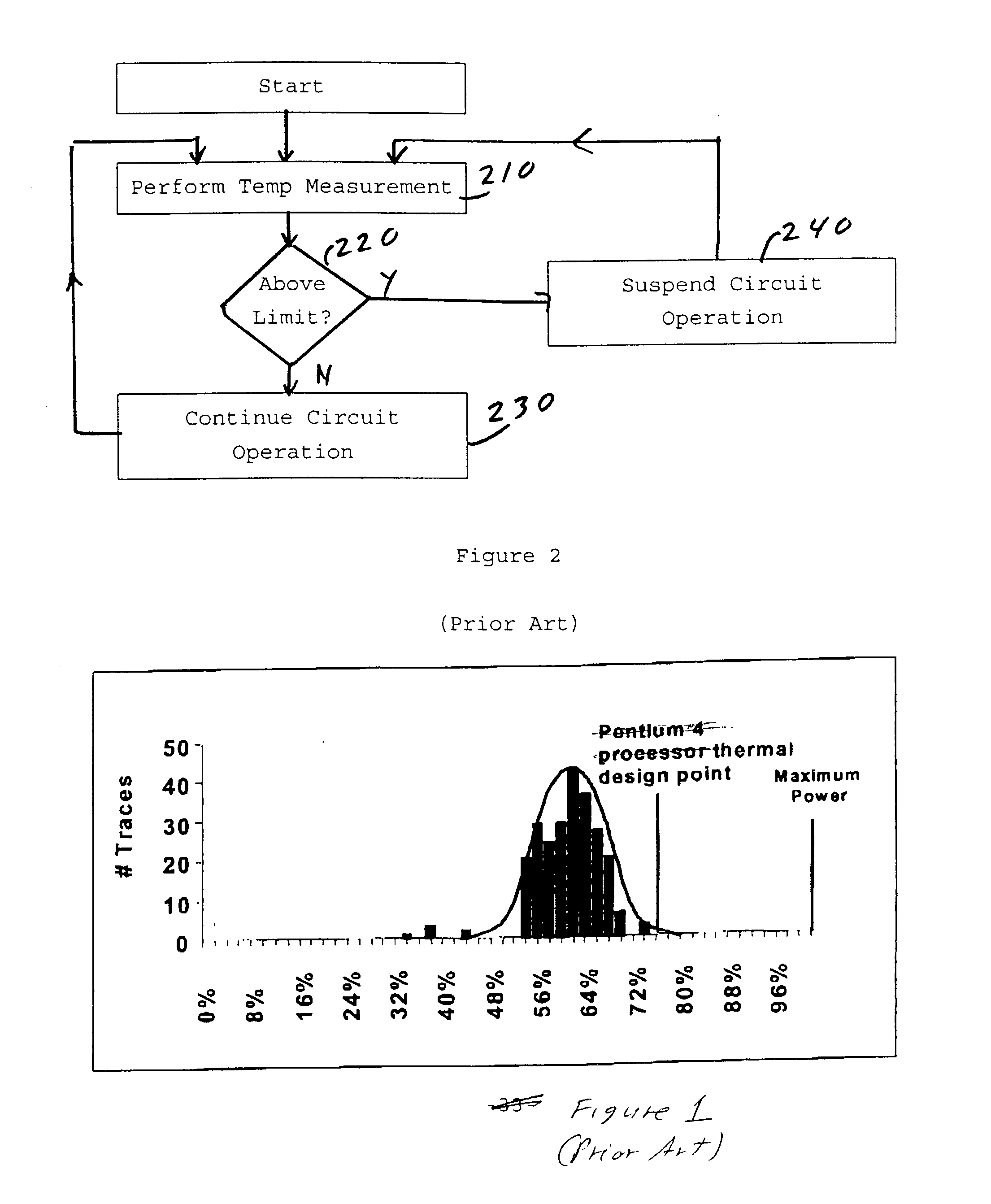
Current microprocessors have only limited ways of responding to overheating (if any at all).
However, this degrades applications in unplanned for ways.
While this solution represents an adequate response to prevent catastrophic failure, its impact on system performance can be quite undesirable.
In particular, increased system temperature can lead to the random reduction of system performance, and wreak havoc on the system, leading to erratic behavior.

Method used


Image

  • Method and apparatus for software-assisted thermal management for electronic systems
  • Method and apparatus for software-assisted thermal management for electronic systems
  • Method and apparatus for software-assisted thermal management for electronic systems

Examples


first embodiment

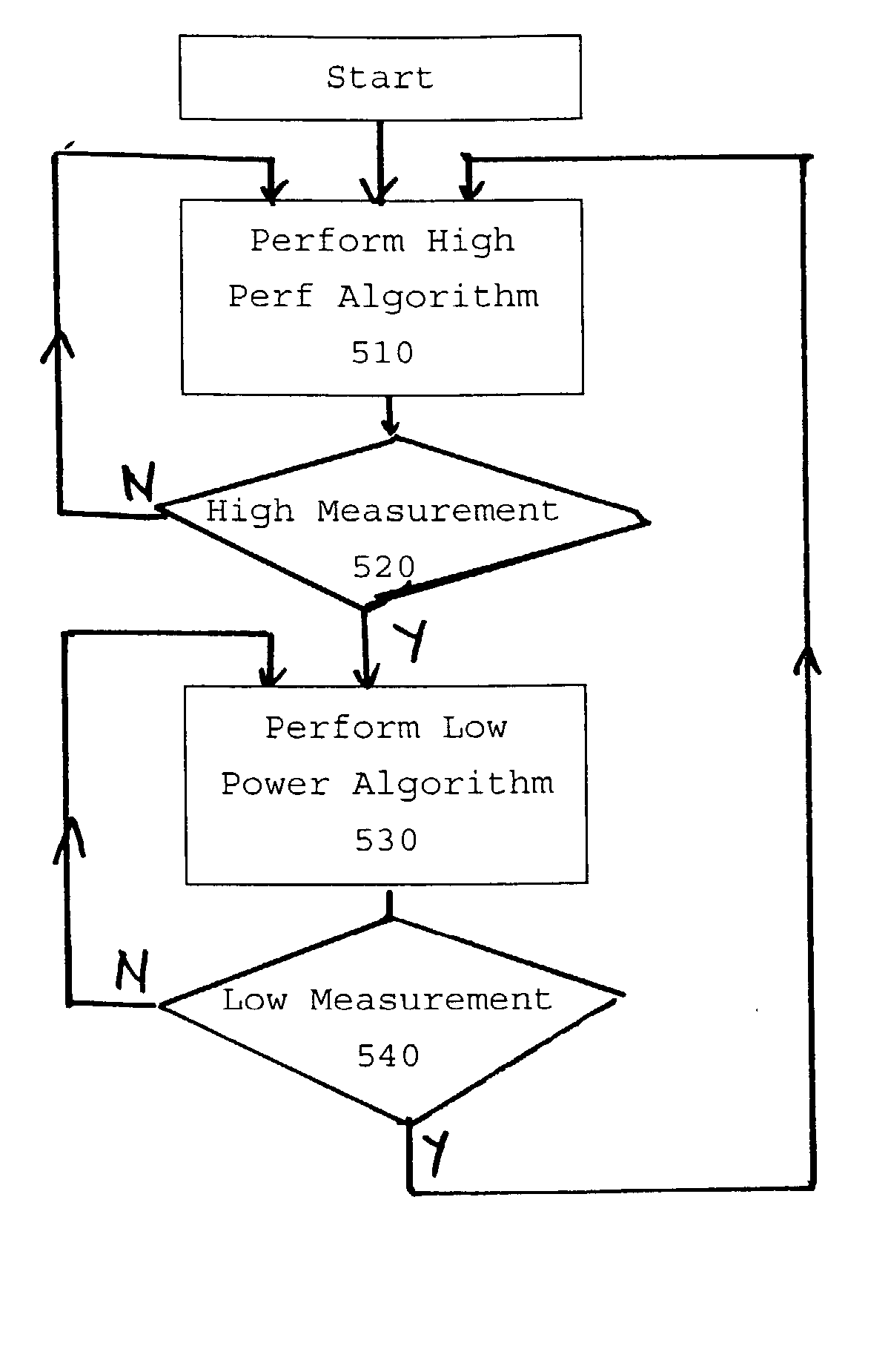
[0055] Referring now to FIG. 5, there is shown software operation in conjunction with a thermal control circuit in accordance with the present invention. The software has been adapted to execute in a first performance-optimized and a second power-optimized mode of operation in response to notification events of a thermal monitor circuit indicating entrance and exit from critical power-dissipation levels.

[0056] Upon system start, software enters processing in step 510. In step 510, the software executes a performance-optimized version of one or more algorithms. In step 520, it is checked whether a notification event indicating critical power-dissipation levels has occurred. If no event is present, then processing continues in step 510. Otherwise, processing transfers to step 530.

[0057] In step 530, a power-optimized version of one or more of the employed algorithm (i.e., an algorithm with lower power dissipation) is employed to continue processing. In step 540, it is checked whether ...

second embodiment

[0060] Referring now to FIG. 6, there is shown software operation in conjunction with a thermal control circuit in accordance with the present invention. The software has been adapted to execute one or more algorithms which have been designed to be guided by a set of configuration parameters which can affect the power dissipation, e.g., the resolution of images drawn, the number of frames drawn per second, etc.

[0061] Upon system start, software enters processing in step 610. In step 610, system initializes the start-up parameters. In step 620, the system performs one or more algorithms under the control of start-up parameters that have been previously determined.

[0062] In step 630, after a time interval that may be fixed or may be adaptable in response to CPU activity, a test is performed to indicate if a notification event indicating a high measurement has occurred. If an event has occurred, control transfers to step 640. Otherwise, control transfers to step 650.

[0063] In step 640,...


PUM


Abstract

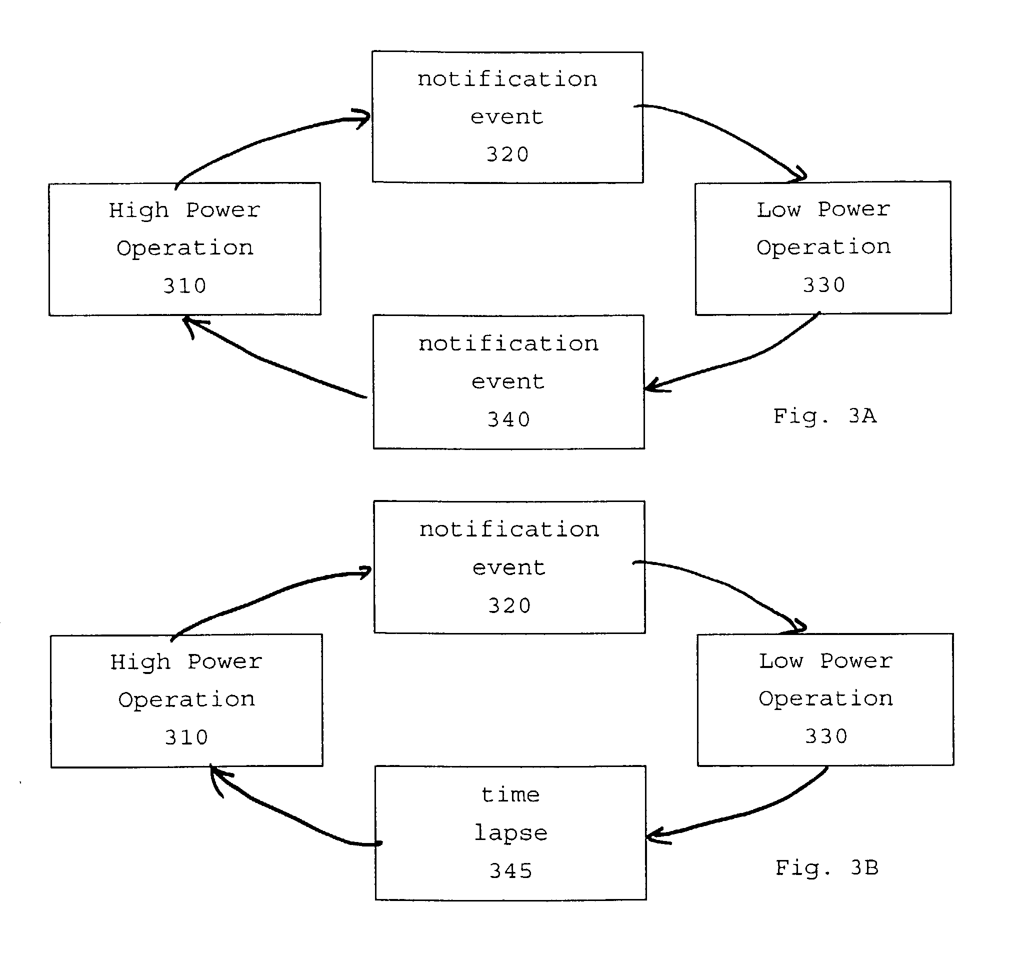
In a computer system, a device for measuring power dissipation (e.g., using on-die thermal sensors) is linked to both a hardware-based thermal management solution and with a means for causing a notification event to software, so that, initially, the operating system software and / or the application software modifies its behavior in response to the notification event to reduce overall system power dissipation and the hardware-based thermal management solution is only triggered if the software solution is not effective; with both operating system and application software resuming higher-performance algorithms when power dissipation is no longer critical.

Description

[0001] 1. Field of the Invention[0002] The present invention generally relates to power and power-density management in microprocessors, and more particularly to a method and apparatus for a power and thermal management employing software and hardware components.Description of the Related Art[0003] In the last decade, the microprocessor power dissipation has gone up by a factor of ten. The frequency of operation of CMOS devices has increased ten fold. While the input voltage and capacitance of devices has decreased, the number of devices on a typical microprocessor die has increased by an order of magnitude. Moreover, device miniaturization has led to integration of cache contained at a multi-chip level to one contained on the microprocessor die. This has resulted in high CPU core power density--e.g., 50% of a 20 mm by 20 mm micro-processor die may contain the CPU core, with the rest being cache. The total power dissipation from such a microprocessor has reached 100 W, and the power...

Claims


Application Information

Patent Timeline
IPC IPC(8): G06F1/20
CPCY02B60/1275G06F1/206Y02D10/00
Inventor GSCHWIND, MICHAEL KARLSALAPURA, VALENTINA
Owner FOCUS GLOBAL SOLUTIONS LLC
Learn More