Measuring tool, encoder and producing method of encoder

a technology of encoder and measuring tool, which is applied in the direction of mechanical measuring arrangement, instruments, applications, etc., can solve the problems of increased production cost, complex production line, and increased time and cost for machining metal down into desired shap

Inactive Publication Date: 2003-11-27
MITUTOYO CORP
View PDF12 Cites 27 Cited by
  • Summary
  • Abstract
  • Description
  • Claims
  • Application Information

AI Technical Summary

Problems solved by technology

However, great amount of time and cost are required for machining metal down into a desired shape.
Since such measuring tool experiences many accurate processing during production process, the production line becomes complicated and production cost can be increased.
However, the measurement error by the linear expansion inevitably occurs in a severe measuring environment under hot and low temperature.
Further, when the measuring tool is grasped by hand, different linear expansion occurs on account of different temperature distribution by hand, which results in measurement error.
Further, a measuring tool having a slide mechanism such as a caliper gauge is likely to be worn after repeated use.
Lubricant has to be used for reducing friction to maintain smooth slide movement, which is likely to cause adhesion of dust etc.
However, since the main scale 15 is bonded on the main beam 11, the main scale 15 may be curved or the main scale 15 may be peeled off from the main beam 11, which can result in error in the detected value.
The above problem is not restricted to a digital caliper gauge but also occurs in a measuring tool having an encoder for detecting relative movement of a movable component relative to a fixed component such as a digital micrometer and a digital dial gauge.

Method used


Image

  • Measuring tool, encoder and producing method of encoder
  • Measuring tool, encoder and producing method of encoder
  • Measuring tool, encoder and producing method of encoder

Examples


first embodiment

[0096] [First Embodiment]

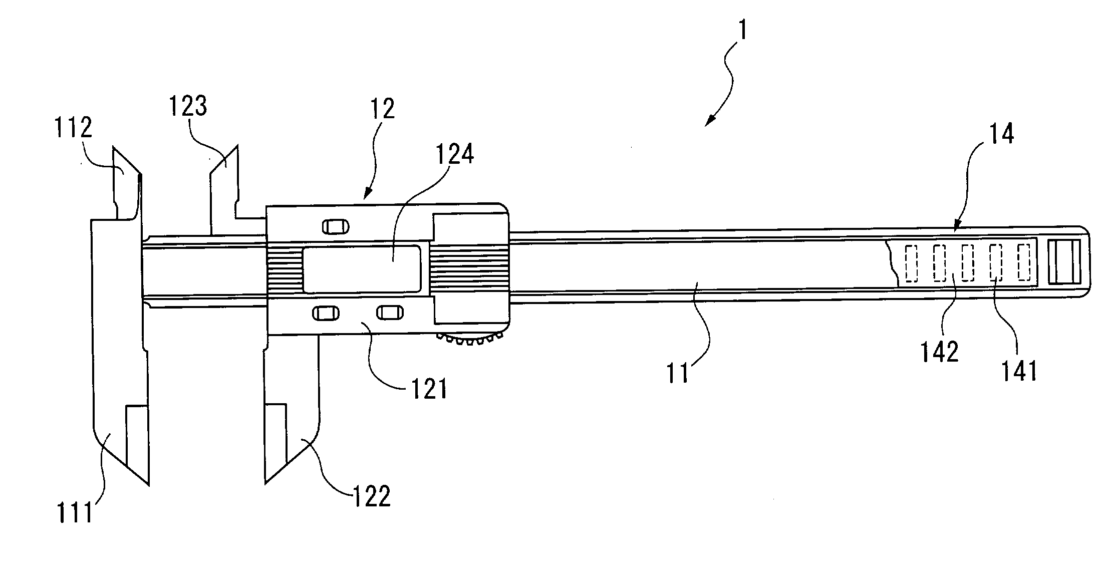
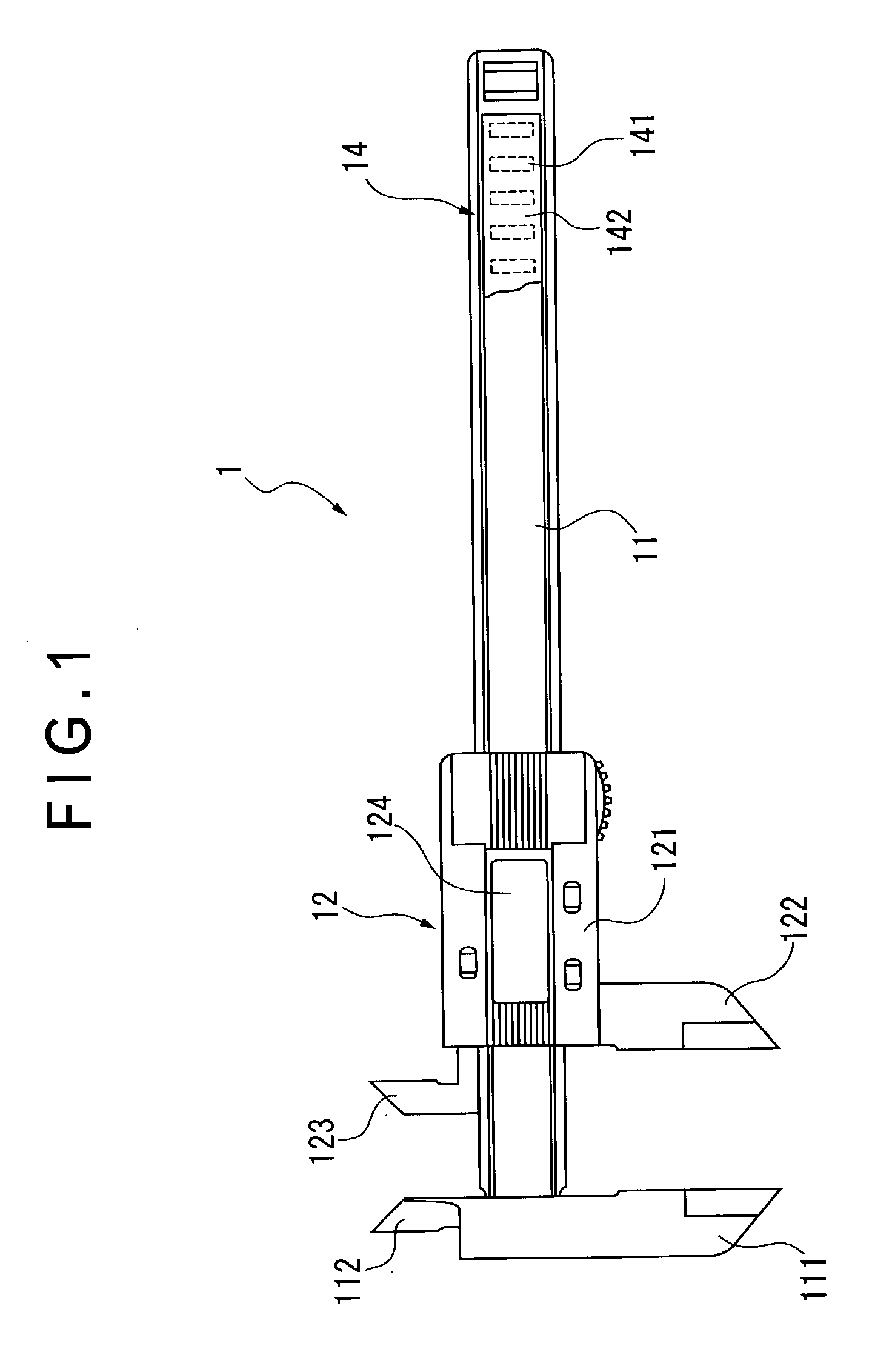
[0097] FIG. 1 shows a digital caliper gauge 1 having an encoder according to a first embodiment of the present invention.

[0098] The caliper gauge 1 has a longitudinal main beam 11 as a base, and a slider 12 as a movable component (slide body) slidable along the longitudinal direction of the main beam 11.

[0099] The main beam has an outside-measuring jaw 111 and an inside-measuring jaw 112 provided on a longitudinal end of the main beam 11 and a main scale 14 of an electrostatic encoder provided along the longitudinal direction of the main beam 11.

[0100] The main beam 11 is molded integrally with the outside-measuring jaw 111 and the inside-measuring jaw 112 by injection molding of synthetic resin by polystyrene containing carbon nanofiber as a nanoscale compound.

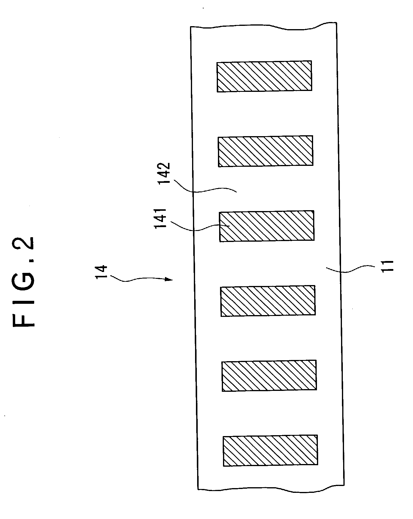
[0101] As shown in enlarged illustration of FIG. 2, the main scale 14 is an electrode pattern consisting of an electro-conductive portion 141 as an electrode formed along the longitudinal direction of...

second embodiment

[0125] [Second Embodiment]

[0126] FIG. 4 shows a dial gauge 2 as a second embodiment of measuring tool according to the present invention. FIG. 4 is an illustration of the dial gauge 2 with back lid thereof being detached. Though a dial gauge is taken as an example in the present embodiment, a micrometer may also be constructed in the same manner.

[0127] The dial gauge 2 has a case body 21, a spindle 22 as a slide body penetrating the outer circumference of the case body 21 and being slidably supported in the axial direction thereof, a power transmitting portion 23 for transmitting the displacement of the spindle 22 as a power and a non-illustrated display for displaying the transmitted power as a displacement amount of the spindle 2.

[0128] The case body 21 has a bushing 211A as a slide guide for slidably guiding the spindle 22 in the axial direction and a stem 212 protruding downward in FIG. 4. An engaging groove 213 is formed along slide direction of the spindle 22 on the inner circ...

third embodiment

[0142] [Third Embodiment]

[0143] FIG. 6 shows a linear encoder 3 used for movement amount measuring tool according to the present invention. FIG. 6 is a cross section of the linear encoder 3.

[0144] The linear encoder 3 has a frame 31 as a base, a scale 32 provided on the frame 31, a slide 33 as a slide body capable of slide movement relative to the frame 31, a detector 34 moving together with the slide 33 to detect the movement relative to the scale 32, a roller slider 35 as a slide guide provided on the slide 33 for guiding the slide movement of the slide 33 while being in contact with the frame 31 and the scale 32. In FIG. 6, the slide direction of the slide 33 is perpendicular to the surface of FIG. 6. FIG. 7 shows a side elevational view of the slide 33.

[0145] The frame 31, the slide 33 and the slider 35 are formed by injection-molding of the synthetic resin containing carbon nanofiber. The slider 35 is formed by injection-molding of the synthetic resin containing carbon nanofibe...


PUM


Abstract

Components of a measuring tool such as a main beam (11) and a slider (12) of a caliper gauge (1) are formed by a synthetic resin containing carbon nanofiber and an electro-conductive electrode (15) is formed on the surface of the main beam (11) at a predetermined pitch, so that a production process can be simplified, rigidity of the components can be enhanced, linear expansion coefficient can be reduced, and anti-frictional properties can be improved, thus enhancing durability while improving measurement accuracy.

Description

[0001] 1. Field of the Invention[0002] The present invention relates to a measuring tool, an encoder used for the measuring tool and a producing method of the encoder.[0003] 2. Description of Related Art[0004] Various measuring tools for measuring distance, length and angle have been conventionally known. For instance, a caliper gauge is used as a measuring tool for measuring length. A caliper gauge has a main beam having a first measuring jaw, and a slider capable of slide movement along the longitudinal direction of the main beam and having a second measuring jaw to be in contact with a workpiece together with the first measuring jaw.[0005] Maintaining measurement accuracy for a long time is of great importance for such a caliper gauge, and the main beam and the slider may preferably be made of material capable of minute processing and enduring repeated slide movement. Accordingly, the main beam and the slider of a caliper gauge are made of anti-frictional thermally treated metal ...

Claims


Application Information

Patent Timeline
Patent Type & Authority Applications(United States)
IPC IPC(8): G01B1/00G01B3/20G01B5/00G01D5/00G01D5/347
CPCB82Y30/00G01B1/00G01B3/205Y10S977/753G01D5/00G01D5/34707G01B5/0014
Inventor MATSUMIYA, SADAYUKIYOSHIOKA, SUSUMUHAYASHIDA, SHUUJISASAKI, KOUJI
Owner MITUTOYO CORP
Why Eureka
Try Eureka