
Doctor blade system and method

a blade and doctor technology, applied in the field of self-sealing doctor blades, can solve the problems of ink leakage through the blade holder, difficult cleaning, doctor blades and seals becoming caked with ink and/or wear out,

Inactive Publication Date: 2003-11-27
MAX DAETWYLER CORP
View PDF6 Cites 0 Cited by
  • Summary
  • Abstract
  • Description
  • Claims
  • Application Information

AI Technical Summary

Benefits of technology

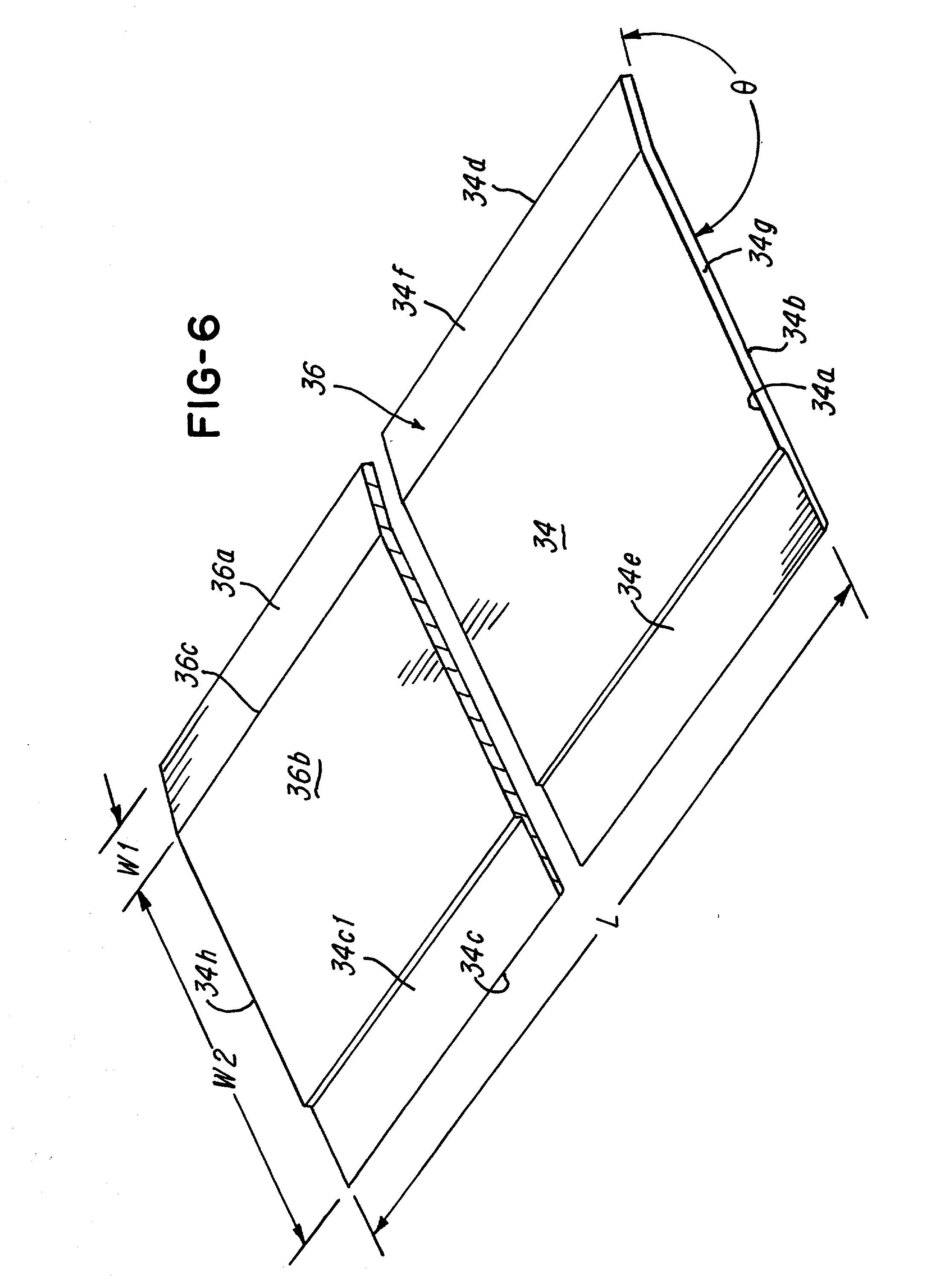
[0009] It is another object of the present invention to provide a doctor blade having an integral non-planar area which facilitates providing at least one continuous contact along a width of the doctor blade.
[0011] Yet another object of the invention is to provide a doctor blade having a non-planar area which facilitates providing a plurality of pressure points on both sides of the doctor blade to facilitate sealing both sides of the doctor blade when it is mounted in a blade holder.
[0012] Still another object of the present invention is to provide a printing press having the aforementioned doctor blade in which the blade prevents migration of ink past the blade holder.
[0017] In yet another aspect this invention comprises a doctor blade comprising a blade member having a first side, a second side, and a non-planar area, and the non-planer area defining at least one contact on the first side so that when the doctor blade is situated in a blade holder in a press, the at least one contact is integral with the blade member and is in substantially continuous pressure engagement with the blade holder to facilitate preventing ink from leaking past at least one of the first side or second side of the blade holder.
[0018] In still another aspect this invention comprises a doctor blade assembly comprising a blade holder for holding a doctor blade, at least one doctor blade is situated in the blade holder, the at least one blade comprising a blade member having a first side, a second side, and a non-planar area; and the non-planar area defining at least one contact on the first side so that when the doctor blade is situated in a blade holder in a press, the at least one contact is in substantially continuous pressure engagement with the blade holder to facilitate preventing ink from leaking past at least one of the first side or second side of the blade holder.

Problems solved by technology

However, the housing is typically made of metal so that the seal between the doctor blade and the metal housing is not good, and ink tends to migrate between the doctor blade and the housing, making it difficult to clean and it causes ink to leak through the blade holder, among other things.
Over time, the doctor blades and seals become caked with ink and / or wear out.
As a result, the doctor blades and 0-ring seals become ineffective for the purpose for which they are intended.
One of the drawbacks of the approaches of the past is cost.
The coatings or tape had to be applied to the doctor blades and the cost of these components was sometimes prohibitive.

Method used


Image

  • Doctor blade system and method
  • Doctor blade system and method
  • Doctor blade system and method

Examples


Embodiment Construction

[0036] Referring now to FIG. 1, a printing system 10 comprising a printing press 12 which rotatably supports a roll or cylinder 14, such as an anilox roll, gravure cylinder or the like, in operative relationship with a doctor blade assembly 16. The doctor blade assembly 16 comprises a bottom 18, first wall 22 and second wall 24 which cooperate to define a well area 26 for receiving ink, lacquer, adhesive or other fluid to be applied to the roll 14. As illustrated in FIG. 1, a surface 14a of cylinder 14 is in operative engagement with the fluid 27 so that the ink may be applied to the surface 14a in a manner conventionally known. In some applications, for example, the surface 14a may have a pattern of cells or cavities (not shown) for receiving ink to print a pattern. It should be understood that the printing press 12 may be a flexographic printing system, gravure printing system, lithographic printing system that requires the application of fluid onto a cylinder.

[0037] The blade hol...


PUM


Abstract

A system and method for sealing a doctor blade is shown. The doctor blade has a non-planar area which facilitates providing at least one substantially continuous contact on one or both sides of the doctor blade to seal the doctor blade when it is situated in a blade holder.

Description

[0001] 1. Field of the Invention[0002] This invention relates to a doctor blade assembly and, more particularly, to a self-sealing doctor blade having a portion which is non-planar in cross-section to provide at least one of continuous contact or pressure point when the blade is situated in a blade holder.[0003] 2. Description of Prior Art[0004] Doctor blades are extensively used in rotary-printing units or presses, especially flexo-graphic units, for applying ink, lacquer, adhesive or the like to a rotating roll or cylinder rotatably mounted in the printing press. In a flexo-graphic or gravure-printing unit, for example, a doctor blade, such as a chamfered doctor blade, serves to ink the screen roller, that is, fill the cells or recesses of the roller with printing ink. The inking of the cylinder is essential for the printing result. It is of particular importance that the cylinder is uniformly inked which means that the distance between the roller and the doctor blade have to be a...

Claims


Application Information

Patent Timeline
Patent Type & Authority Applications(United States)
IPC IPC(8): B41F9/10B41F31/02
CPCB41F31/027B41F9/1072
Inventor OEGERLI, KURT JOHANNSHORES, JOB MARKAS
Owner MAX DAETWYLER CORP
Features
  • Generate Ideas
  • Intellectual Property
  • Life Sciences
  • Materials
  • Tech Scout
  • Unparalleled Data Quality
  • Higher Quality Content
  • 60% Fewer Hallucinations
Learn More