Fuel-heating type fuel injection apparatus and internal combustion engine

Inactive Publication Date: 2003-11-27
HITACHI LTD +1
View PDF0 Cites 39 Cited by
  • Summary
  • Abstract
  • Description
  • Claims
  • Application Information

AI Technical Summary

Problems solved by technology

This makes the system composition complicated, increases its produc

Method used


Image

  • Fuel-heating type fuel injection apparatus and internal combustion engine
  • Fuel-heating type fuel injection apparatus and internal combustion engine
  • Fuel-heating type fuel injection apparatus and internal combustion engine

Examples


first embodiment

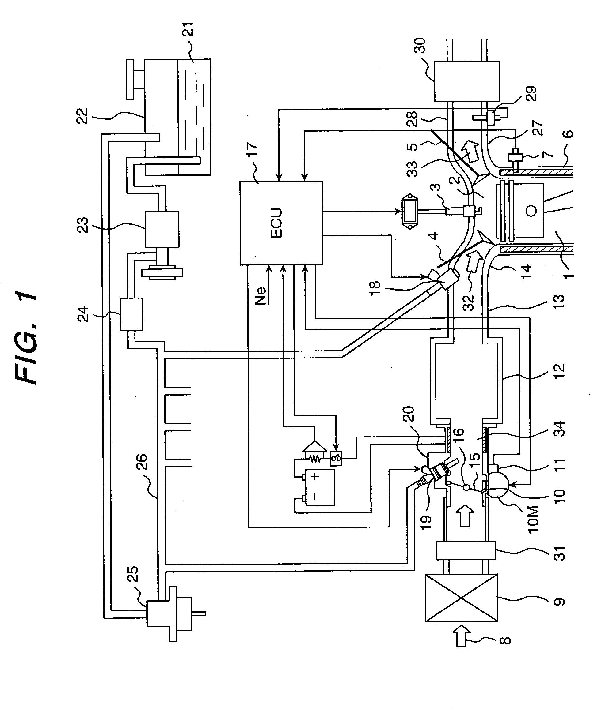
[0048] the present invention will be described referring to FIG. 1 to FIG. 9.

[0049] FIG. 1 is a schematic block diagram of the whole spark ignition type internal combustion gasoline engine equipped with a fuel injection apparatus of the present invention.

[0050] The internal combustion engine 1 has, in each combustion chamber 2, a spark plug 3, an intake valve 4 to take in air, an exhaust valve 5 to discharge exhaust gas after combustion. The engine 1 is equipped with a water temperature sensor 7 on the side of the combustion chamber 2 to sense the temperature of the engine cooling water 6, and a rotation sensor (not shown in the figure) to sense the rotational speed (running status) of the engine.

[0051] The intake system to feed air to the combustion chamber 2 comprises an air flow sensor 31 which measures the flow rate of air taken in through an air cleaner 9 and a motor 10M which is driven in synchronism with the operation of the throttle pedal by the driver or the running status ...

second embodiment

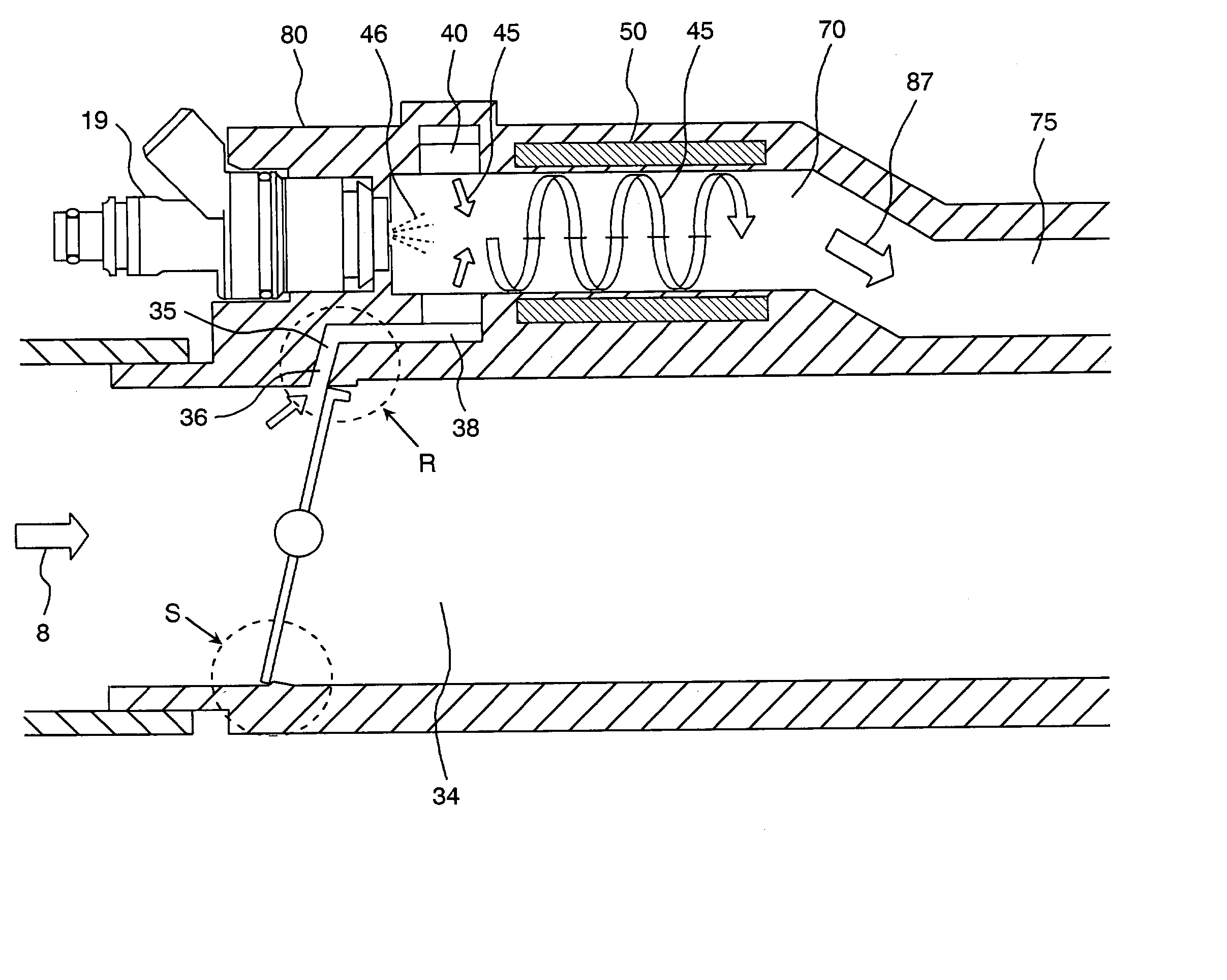
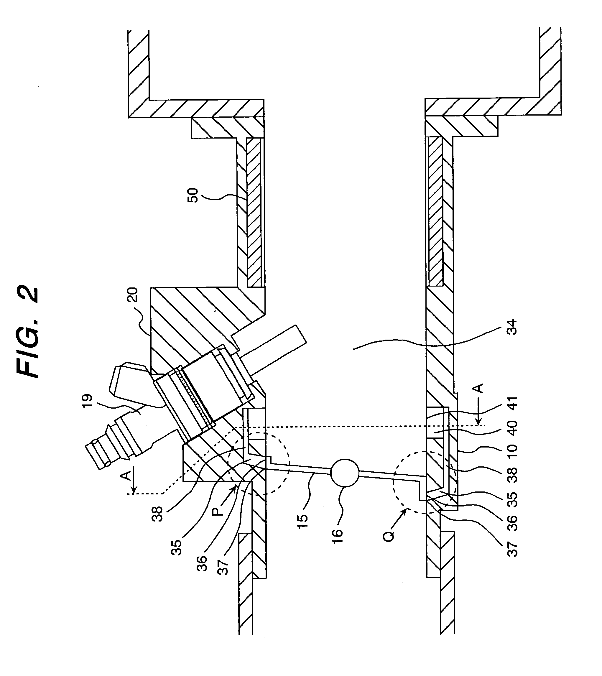
[0074] FIG. 10 shows a fuel injection unit which is the present invention.

[0075] Below will be explained differences between first and second embodiments. The electronically-controlled throttle body 10 containing a throttle valve 15 is provided separately from a single integrated unit 60 containing a secondary fuel injection valve 19 and a heater 50. This single integrated unit 60 mounted between the electronically-controlled throttle body 10 and the intake manifold 13 having a collector 12 on a vehicle. The swirler 40 is provided opposite to the single integrated unit 60 of the electronicallycontrolled throttle body 10.

[0076] The other composition of this embodiment is the same as that of the first embodiment and its explanation is omitted here.

[0077] In accordance with this embodiment, the electronically-controlled throttle body 10, the single integrated unit 60, and the intake manifold 13 having the collector 12 are separately mounted and demounted. This makes their maintenance s...

third embodiment

[0078] FIG. 11 shows a fuel injection unit which is the present invention.

[0079] Below will be explained differences between first and third embodiments. An electronically-controlled throttle body 10 and a heater 50 are assembled in a single unit and mounted on an intake manifold 13 having a collector in its downstream side. The heater 50 is projected into the internal air passage of the integrated intake pipes from a place at which the integrated unit 60 and the collector 12 are joined. In this case, the unit to which the integrated unit 60 is mounted is not limited to the collector. The integrated unit 60 can be mounted on the intake manifold 13.

[0080] In accordance with this embodiment, the heater 50 is projected into the integrated intake pipes. This can reduce the longitudinal length of the main intake passage 34 and make the fuel injection unit smaller. In other words, the fuel injection unit can be mounted on and demounted from a vehicle more easily.


PUM


Abstract

The present invention is to present a fuel-heating type fuel injection apparatus, at the startup of the engine, able to prevent fuel-attaching on the wall of the intake passage and eliminate hydro carbons in the exhaust. A fuel-heating type fuel injection apparatus has a main intake passage for supplying air into cylinders of the internal combustion engine. The main passage is equipped with a throttle valve and a bypass passage for bypassing the throttle valve. On idling operation, when the intake air flows through the bypass passage, the airflow rate is controlled by using the throttle valve, and the airflow is given a swirling force. The swirling airflow is heated mixing with fuel and fed into an internal combustion engine.

Description

[0001] 1. Field of the Invention[0002] The present invention relates to a fuel injection apparatus equipped with a fuel injection valve which injects fuel to an airflow bypassing a throttle valve, heats the fuel-air mixture with a heater, and sends it to an intake passage (pipe) or cylinders and an internal combustion engine equipped therewith.[0003] 2. Prior Art[0004] U.S. Pat. No. 5,482,023 discloses a cold-start fuel control system comprising a cold start fuel injector, a heater, and an idle speed control valve (hereinafter abbreviated as the ISC valve). This system causes a part of air from the ISC valve to mix with fuel injected from the cold-start fuel injector. The fuel from the cold-start fuel injector is, being mixed with air from the ISC valve, fed into a series of cylindrical heaters lined up in the downstream side of the cold-start fuel injector. The fuel is vaporized while passing through the heaters and mixed with air flowing through the main intake passage at the exit...

Claims


Application Information

Patent Timeline
IPC IPC(8): F02D9/02F02D9/10F02D11/10F02M29/06F02M31/135F02M31/18F02M35/10F02M35/108F02M53/00F02M53/02F02M53/06F02M69/04
CPCF02D9/1015F02D9/1055F02M29/06F02M31/135Y02T10/126F02M53/02F02M53/06F02M69/044Y02T10/146F02M31/18Y02T10/12
Inventor SAEKI, HIROAKIICHIHARA, TAKANOBUWATANABE, KENJI
Owner HITACHI LTD
Why Eureka
Try Eureka