Excimer or molecular fluorine laser system with multiple discharge units

Inactive Publication Date: 2003-11-27
LAMBDA PHYSIK
View PDF19 Cites 59 Cited by
  • Summary
  • Abstract
  • Description
  • Claims
  • Application Information

AI Technical Summary

Problems solved by technology

Achromatic imaging optics for this wavelength region are difficult to produce.
This would entail an increased thermal load on intracavity opt

Method used


Image

  • Excimer or molecular fluorine laser system with multiple discharge units
  • Excimer or molecular fluorine laser system with multiple discharge units
  • Excimer or molecular fluorine laser system with multiple discharge units

Examples


Embodiment Construction

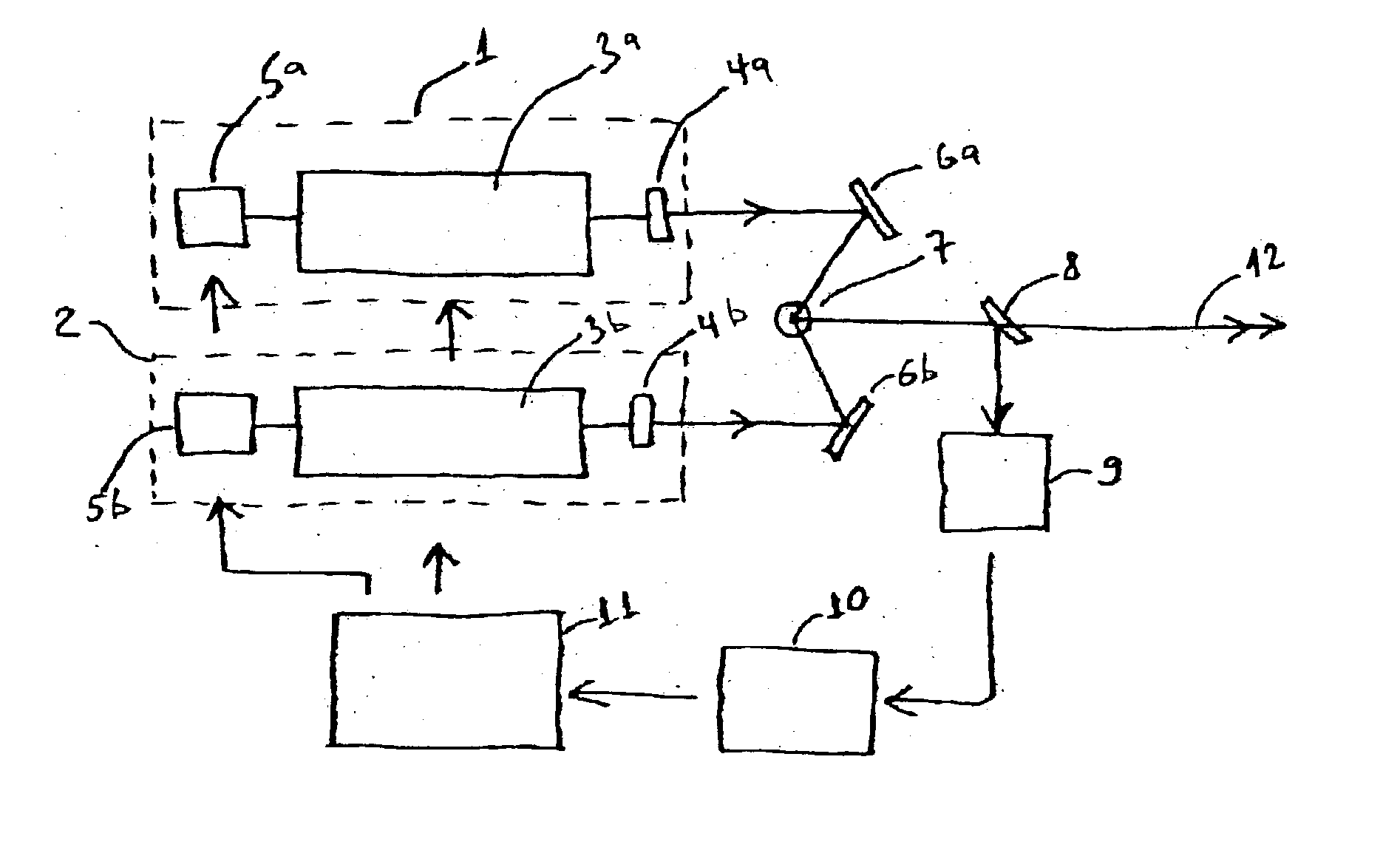
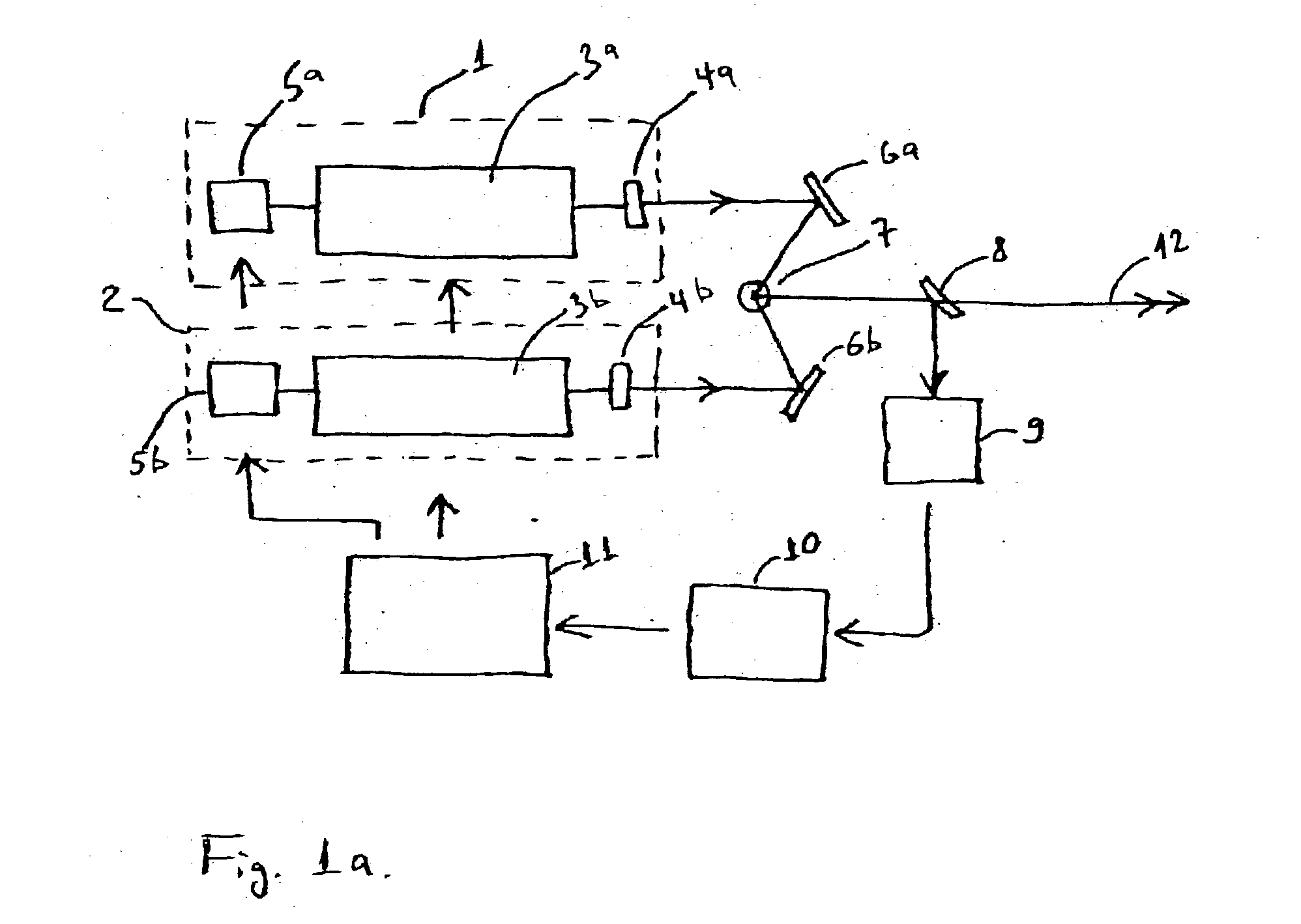
[0019] Systems and methods are provided for combining at least two pulsed excimer or molecular fluorine laser beams from different lasers to obtain a composite beam having a higher power than any of the individual lasers. The peak power may be increased by overlapping the pulses, or the repetition rate may be increased by resolving the pulses, or a combination of both. For example, a pair of 4 kHz lasers may be used for emitting a pair of 4 kHz beams that are combined to form a combined 8 kHz beam or a combined 4 kHz beam having twice the power of each of the two original 4 kHz beams. The at least two beams impinge a beam combining optic or beam combining optics, hereinafter referred to as the beam combiner.

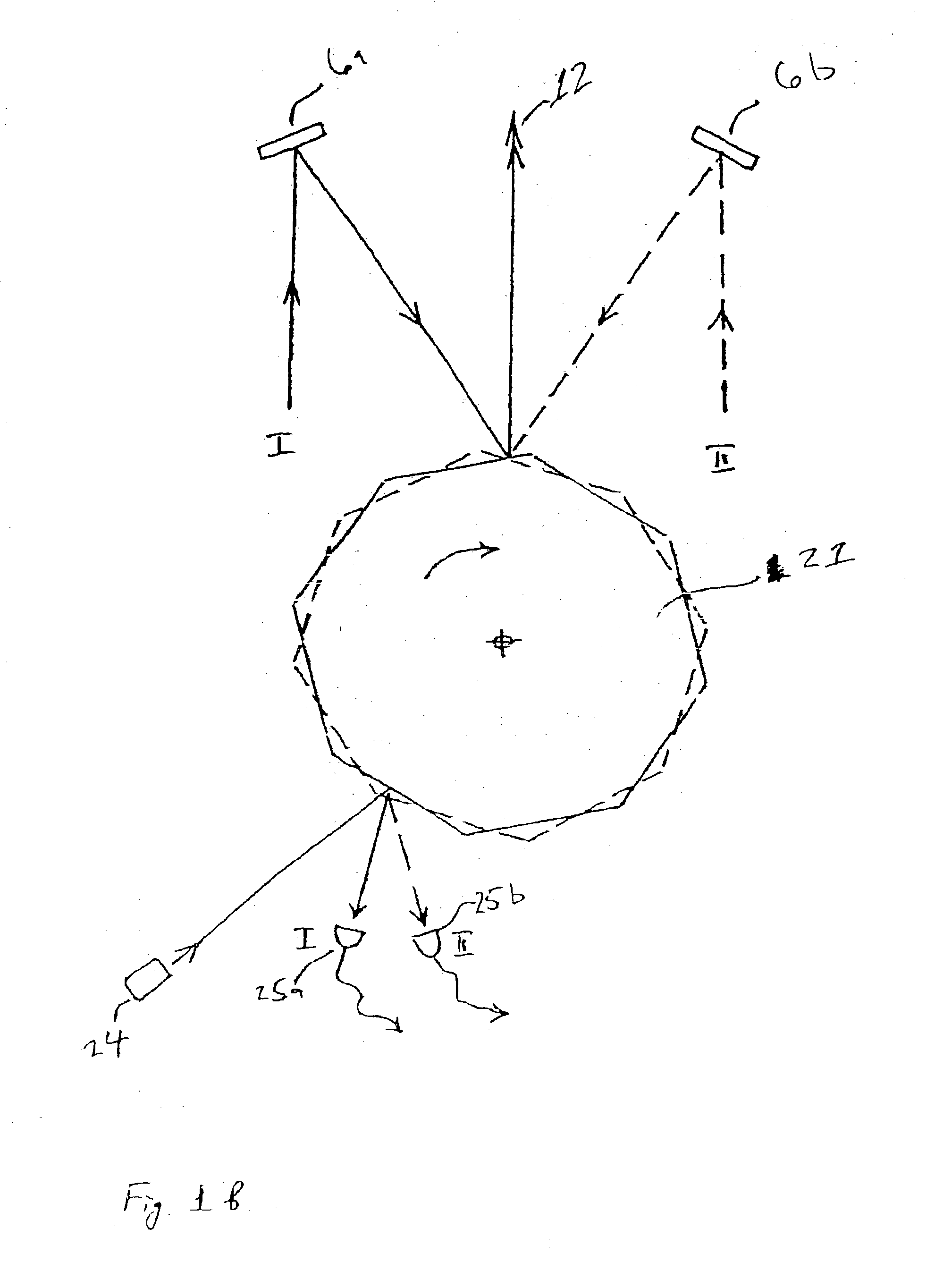
[0020] The beam combiner is configured to combine the at least two beams emitted from the at least two lasers that are each incident from different directions into a composite beam, i.e., combined to be directed along a substantially common optical path. The two beams are synchro...


PUM


Abstract

A sub-310 nm lithography radiation source includes first and second beam generating modules for generating first and second pulsed beams, a beam combiner optic for producing a single combined beam from the first and second pulsed beams, and optics for directing each of the first and second pulsed beams to be incident upon the beam combiner.

Description

PRIORITY CLAIM[0001] The present application claims priority to U.S. Provisional Patent Application Serial Nos. 60 / 382,490, filed May 21, 2002, and 60 / 399,797, filed Jul. 30, 2002, and 60 / 419,176 filed Oct. 15, 2002, the disclosures of which are incorporated herein by reference.[0002] 1. Field of the Invention[0003] The invention provides an excimer or molecular fluorine laser, or an EUV generating source, with two or more discharge or pulse generating modules, where the output beams of multiple modules are combined spatially, and / or temporally, into a single output beam.[0004] 2. Description of the Related Art[0005] Line narrowed excimer lasers are applied in the art of photolithography for production of integrated circuits. Achromatic imaging optics for this wavelength region are difficult to produce. For this reason line-narrowed excimer laser radiation is used for photolithography in order to prevent errors caused by chromatic aberration. Typical, acceptable bandwidths for diffe...

Claims


Application Information

Patent Timeline
IPC IPC(8): G03F7/20G21K1/06H01S3/225H01S3/23
CPCG03F7/70025G03F7/70041G03F7/7005H01S3/2383H01S3/225H01S3/2258H01S3/2366G21K1/06
Inventor BASTING, DIRK L.GOVORKOV, SERGEI V.
Owner LAMBDA PHYSIK
Why Eureka
Try Eureka