Constant current source having a controlled temperature coefficient

Inactive Publication Date: 2003-12-25
MEDIATEK INC
View PDF0 Cites 23 Cited by
  • Summary
  • Abstract
  • Description
  • Claims
  • Application Information

AI Technical Summary

Problems solved by technology

However, temperature changes typically decrease the gain or transconductance of acti

Method used


Image

  • Constant current source having a controlled temperature coefficient
  • Constant current source having a controlled temperature coefficient
  • Constant current source having a controlled temperature coefficient

Examples


Embodiment Construction

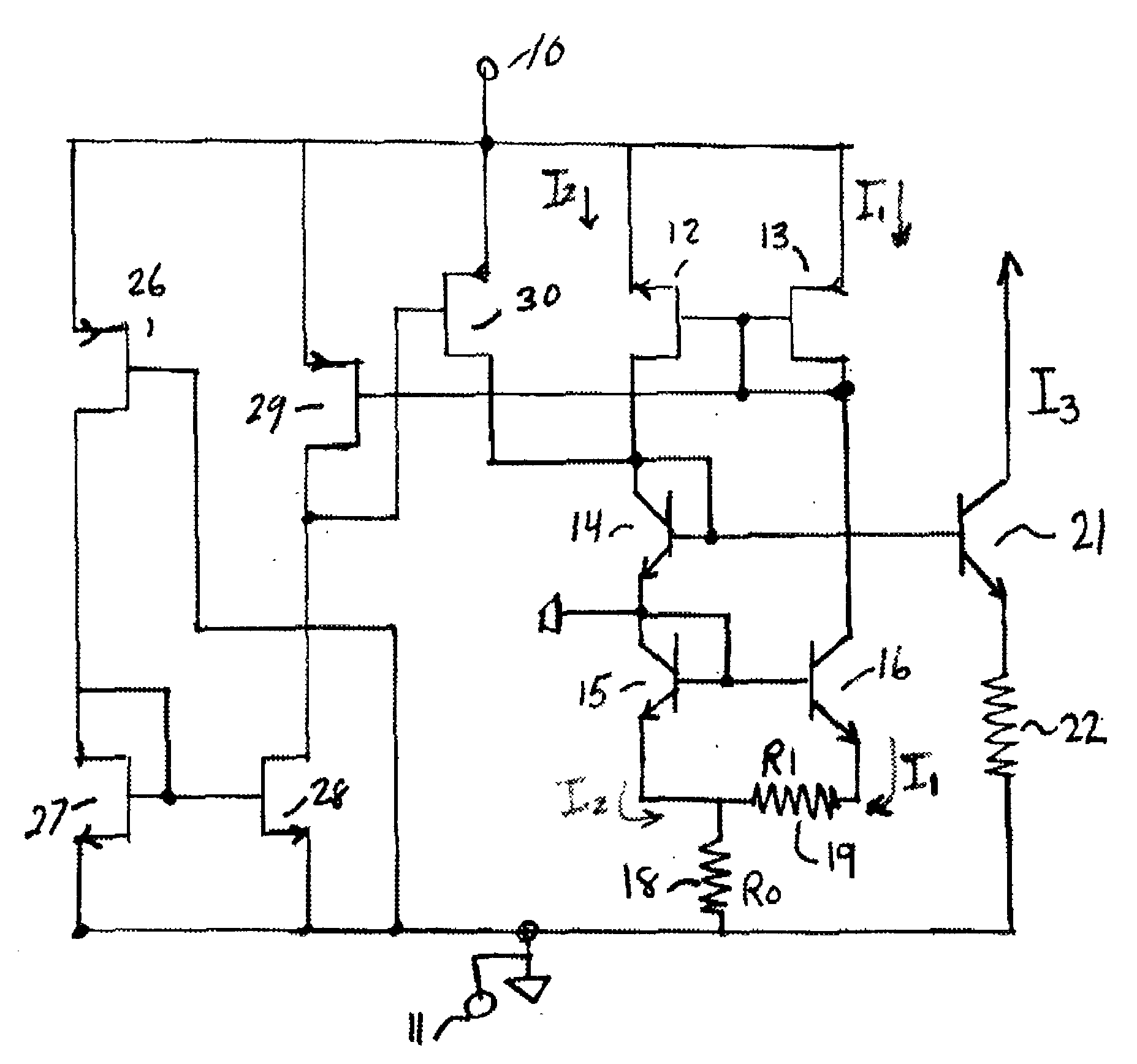
[0005] The schematic circuit drawing of the FIGURE illustrates a bandgap voltage generator connected to a current source. The bandgap voltage generator comprises a pair of bipolar transistors 15 and 16 fed from a current mirror comprising a PFET 12 and PFET 13. The current mirror produces first and second identical currents I.sub.1 and I.sub.2. I.sub.1 is supplied to the collector connection of NPN bipolar transistor 16, and I.sub.2 is supplied through a bipolar NPN transistor 14 to the collector connection of NPN bipolar transistor 15 of the bandgap voltage generator. Resistor 19 having a resistance value R.sub.1 is connected across the emitter connection of NPN bipolar transistors 15 and 16, and resistor 18 having resistance value R.sub.0 receives currents I.sub.1 and I.sub.2 and is connected to the common terminal 11 of the circuit. A power supply voltage is connected across terminal 10 and 11 to provide operating current for the device. The bandgap voltage generated at the base ...


PUM


Abstract

A bandgap circuit for producing a constant current having a controllable temperature coefficient. A current mirror supplies first and second substantially identical currents to first and second bipolar transistors. A first resistor is connected across the emitters of the bipolar transistors. A second resistor connects one to the bipolar emitters to a common terminal where the current source currents are recombined and supplied to a common terminal of a power supply. The band gap voltage produced at the common base connections of the bipolar transistors have a voltage temperature coefficient which is controlled by the values of the resistors. A current source is coupled to receive the bandgap voltage and produces a current having a temperature coefficient corresponding to the voltage temperature coefficient of the bandgap voltage.

Description

BACKGROUND OF INVENTION[0001] The present invention relates to a constant current source for use in radio frequency circuits. Specifically, a current source having a controllable temperature coefficient is described.[0002] Radio frequency circuit applications for the cellular telephone field may require circuits which can operate over a wide temperature range. In the case of a transmitter circuit for a radio telephone, it is desirable to maintain a power output characteristic constant so that the compression point is stable with temperature. However, temperature changes typically decrease the gain or transconductance of active devices in the circuit, even when current is maintained constant over temperature. The loss in gain will decrease the compression point for an amplifier biased to operate in a class A mode of operation. As the compression point decreases, increased input signal levels do not increase the output signal level proportionally. It may be desirable in some applicati...

Claims


Application Information

Patent Timeline
IPC IPC(8): G05F3/30
CPCY10S323/907G05F3/30
Inventor ESHRAGHI, ARIAWANG, XIAODONG
Owner MEDIATEK INC
Why Eureka
Try Eureka