

Refrigerant cycle with ejector
a technology of refrigerant cycle and ejector, which is applied in the direction of refrigeration components, machine operation mode, lighting and heating apparatus, etc., can solve the problems of large change in the pressure of high-pressure refrigerant, excessive increase in refrigerant pressure, and deterioration of the efficiency of the refrigerant cycl
- Summary
- Abstract
- Description
- Claims
- Application Information
AI Technical Summary
Benefits of technology
Problems solved by technology
Method used
Image

Examples
first embodiment
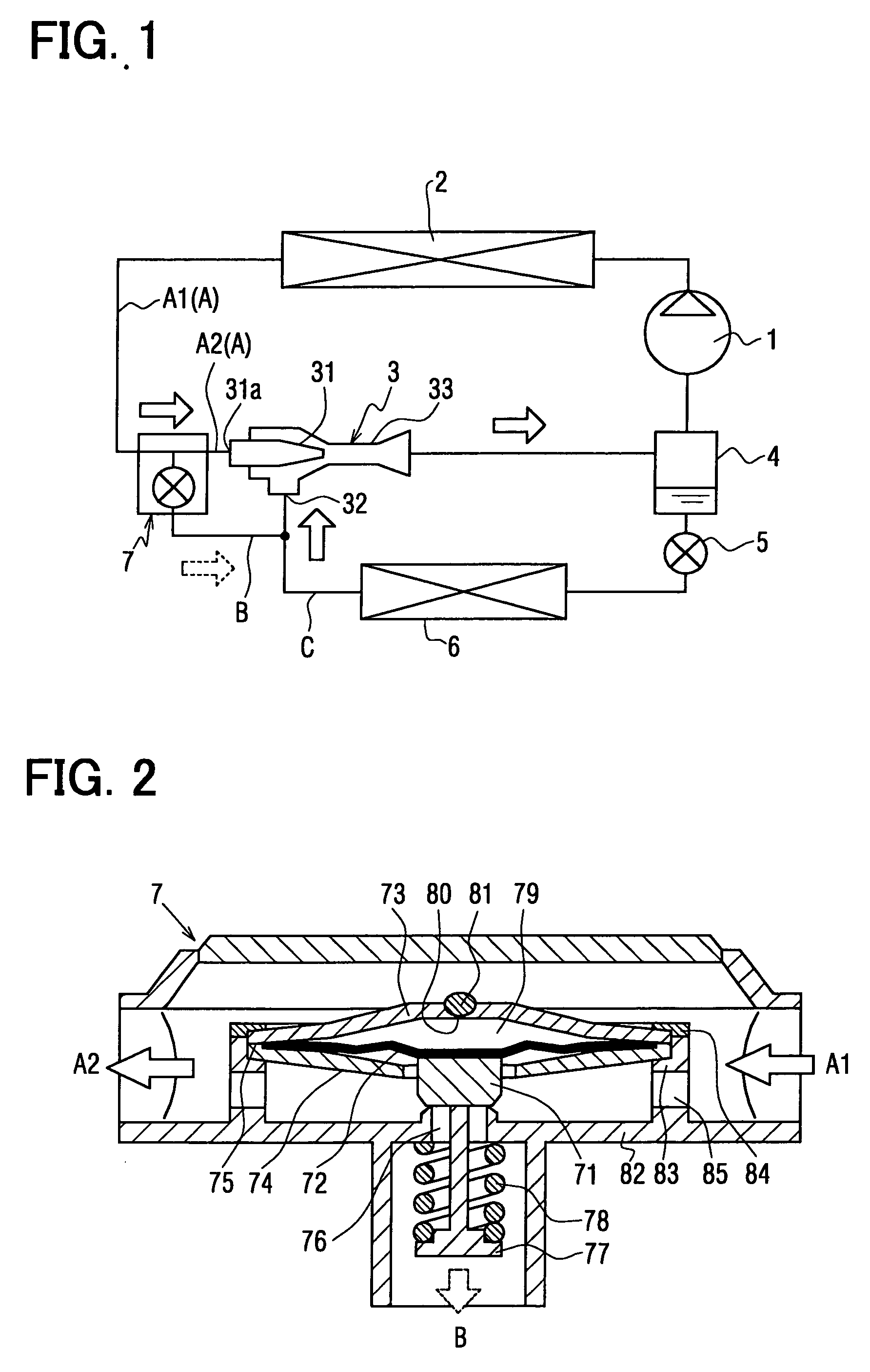
[0030] (First Embodiment)
[0031] In the first embodiment, carbon dioxide is typically used as refrigerant in a refrigerant cycle. As shown in FIG. 1, a compressor 10 is disposed for sucking and compressing refrigerant circulated in the refrigerant cycle. A radiator 2 is a high-pressure heat exchanger for cooling high-temperature and high-pressure refrigerant discharged from the compressor 10 by performing heat-exchange operation between air (e.g., outside air) blown by a blower and the high-temperature and high-pressure refrigerant. An ejector 3 is disposed for decompressing refrigerant from the radiator 2, and a gas-liquid separator 4 is disposed to separate refrigerant discharged from the ejector 3 into gas refrigerant and liquid refrigerant. Further, an evaporator 6 is a low-pressure heat exchanger in which refrigerant is evaporated by absorbing heat from air (e.g., inside air) blown by a blower (not shown). A flow control valve 5 is disposed in a refrigerant passage between the g...
second embodiment
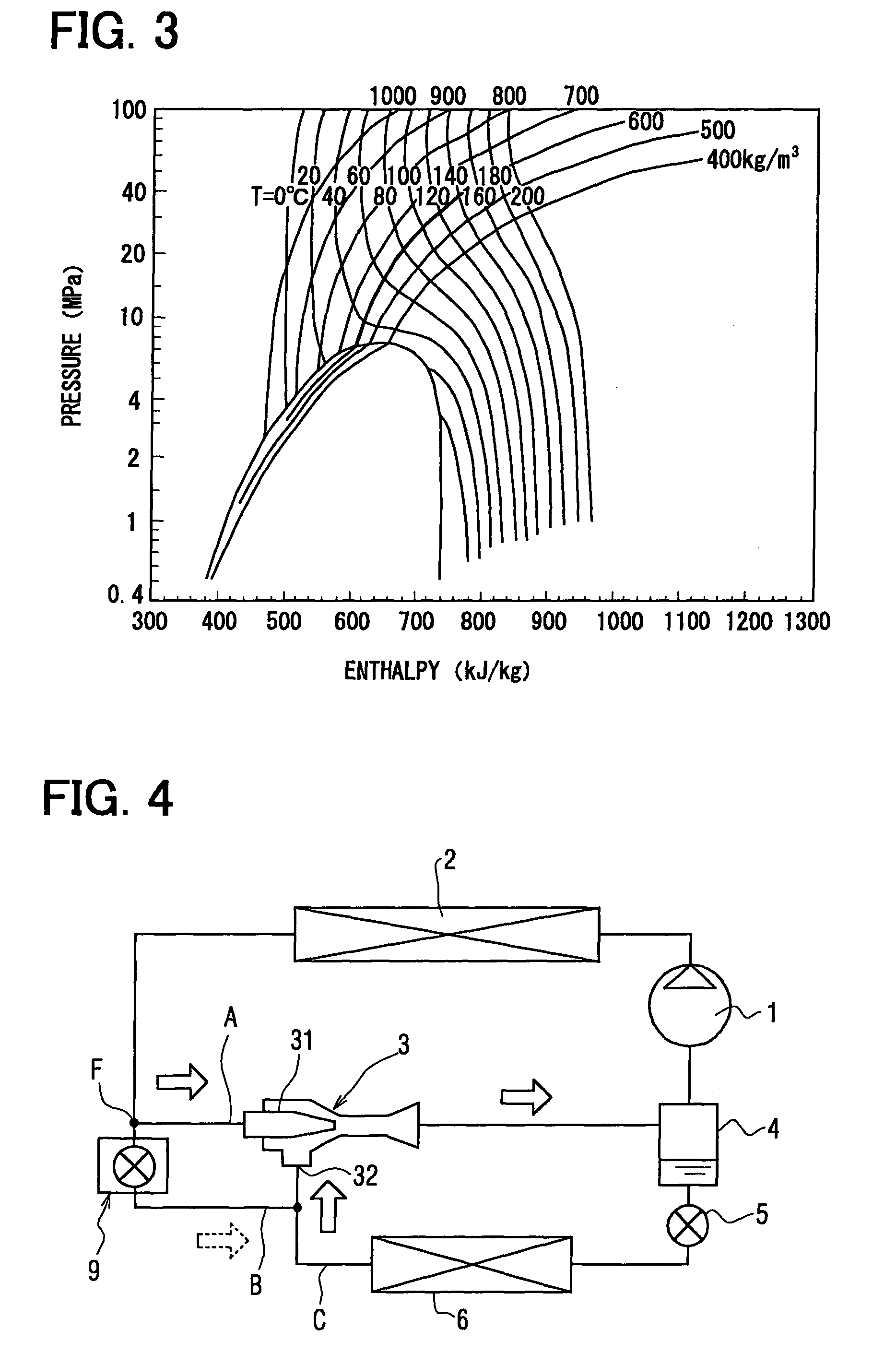
[0045] (Second Embodiment)
[0046] The second embodiment of the present invention will be now described with reference to FIGS. 4-6. In the second embodiment, a control valve 9 having a structure different from that of the control valve 7 of the first embodiment is used, but the other parts are similar to those of the above-described first embodiment. In the second embodiment, the control valve 9 is a differential pressure valve as shown in FIG. 5. The control valve 9 includes a housing 91 made of a metal such as a stainless steel. The housing 91 has an inlet 92 communicating with a branch point F that is provided in the high-pressure refrigerant passage A for connecting the radiator 2 and the nozzle 31 of the ejector 3, and an outlet 95 communicating with the bypass passage B. The bypass passage B is connected to the refrigerant passage C between the evaporator 6 and the suction portion 32 of the ejector 3. Therefore, the housing 91 of the control valve 9 defines a part of the bypass...
third embodiment
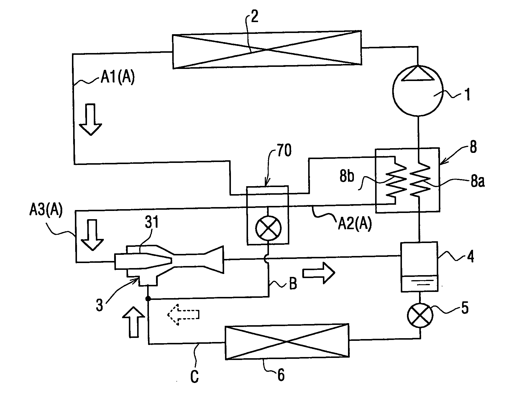
[0054] (Third Embodiment)
[0055] The third embodiment of the present invention will be now described with reference to FIGS. 7 and 8. As shown in FIG. 7, in the third embodiment, an inner heat exchanger 8 for performing heat exchange between refrigerant to be sucked to the compressor 1 and high-pressure refrigerant flowing from the radiator 2 is added, as compared with the refrigerant cycle of the above-described first embodiment. The inner heat exchanger 8 is formed by brazing plural aluminum plates, for example. The inner heat exchanger 8 has therein a first refrigerant passage 8a through which refrigerant to be sucked into the compressor 1 from the gas-liquid separator 4 flows, and a second refrigerant passage 8b through which high-pressure refrigerant flowing from the radiator 2 flows. Generally, a flow direction of refrigerant flowing through the first refrigerant passage 8a is opposite to that flowing through the second refrigerant passage 8b in the inner heat exchanger 8. When...
PUM
 Abstract
Description
Claims
Application Information