
Safety needle apparatus

a needle and safety technology, applied in the field of safety shields, can solve the problems of inconvenient needle use, high risk of blood-borne pathogens from infected patients, and high risk of needle exposure by professionals

Inactive Publication Date: 2004-01-22
CARDINAL HEALTH IRELAND UNLTD
View PDF3 Cites 7 Cited by
  • Summary
  • Abstract
  • Description
  • Claims
  • Application Information

AI Technical Summary

Benefits of technology

[0012] The transport position is a releasably retained position and the needle is protected from inadvertent exposure. It is contemplated that an arrow will be molded into a barrel of the safety needle apparatus and universal lock or unlock symbols will be molded on the shield. In the transport position, the arrow of the barrel will be lined up with the unlocked symbol indicating that the safety needle apparatus is in the transport position and not a permanent final lock position. The shield can be moved between the transport position to an active position as deemed necessary by the clinician for additional injections.
[0013] During the administration of the medication, additional medication cartridges may be required. By placing the shield in the transport position the safety needle apparatus can be safely removed from a syringe holder and the used cartridge removed and replaced with a new cartridge. The safety needle apparatus is reattached and employed for subsequent injections.
[0017] Other advantages of the present disclosure include manipulation of the safety needle apparatus to the transport and final lock positions without the use of buttons or levers. This configuration avoids associated risks that could result in hazardous exposure to the needle. The shield can be designed with a small inner diameter cylindrical surface at its distal end. Needles that are intentionally or unintentionally bent by the user during injections will be contained within this inner diameter cylindrical surface. This feature maintains the point of the needle facing forward and minimizes piercing of the side wall of the shield. This feature also allows the clinician to re-enter the active position without causing additional bending of the needle or puncturing of the shield.
[0018] A cylindrical section can be molded on the barrel near the distal end. The cylindrical section is designed to create a contact fit with the inner diameter surface of the distal end of the shield. This contact fit serves as a moisture barrier when the shield is retracted and the needle is exposed. By blocking the path of the moisture from the patient's mouth to the inside of the shield, the occurrence of shield fogging can be eliminated. Desirably, the safety needle apparatus has a narrow, low profile design allowing minimally restricted access to the patient's mouth and gum areas and allows a clear line of site for injections.
[0019] Another advantage of the safety needle apparatus of the present disclosure is avoidance of a clinician's hands being in the direct path of an exposed needle. This is particularly beneficial when the clinician attempts to remove a cap or sheath from a distal end of the safety needle apparatus. For example, the sheath may engage the shield of the safety needle apparatus in an interference fit. The clinician can manipulate the sheath in the distal direction such that the shield slides forward with the sheath and into the transport position. Once the shield is in the transport position, continued application of force on the sheath will detach the sheath from the shield and allow removal. The distal end of the needle will be surrounded by the shield to avoid accidental needlesticks. In another example, the clinician can slide the shield into the transport position by grasping the shield and sliding it in the distal direction. Once in the transport position, the sheath can be safely removed because the protective shield surrounds the needle.
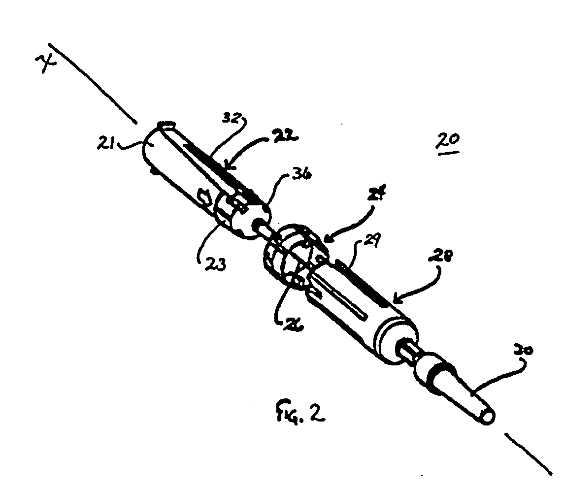
[0021] In an alternate embodiment, the first cylinder includes a barrel and the second cylinder includes a shield mounted to an outer surface of the barrel. The second cylinder may include an elongated shield configured to enclose the needle and a locking ring mounted to a proximal end of the shield. The locking ring defines the key about an inner circumferential surface thereof. The shield may include at least one proximally extending tab that facilitates mounting of the shield within the lock ring. The shield can include a plurality of proximally extending tabs that facilitate mounting of the shield within the lock ring. The tab may be flexibly cantilevered from the shield.

Problems solved by technology

These risks are some of the most prevalent occupational health hazards among healthcare professionals.
These professionals are in danger of contracting such blood-borne pathogens from infected patients by inadvertent needle sticks from a contaminated needle employed during dental, medical, laboratory, etc. procedures.
These type of structure, however, can require button or lever activation that is prone to accidental engagement resulting in hazardous needle exposure.
These configurations, however, may disadvantageously interfere with a procedure or expose the distal end of the needle after use resulting in hazardous exposure to the needle.
These type devices, however, do not allow re-exposure of the distal end of the needle for multiple injection procedures, during transport, etc.
Further, these devices may disadvantageously require complex relative movements of the barrel and shield to effect locking.
The above mentioned devices may suffer from additional drawbacks such as needle bending during use and moisture buildup on the shield, which can prevent visual inspection of needle travel during a procedure.

Method used


Image

  • Safety needle apparatus
  • Safety needle apparatus
  • Safety needle apparatus

Examples


Embodiment Construction

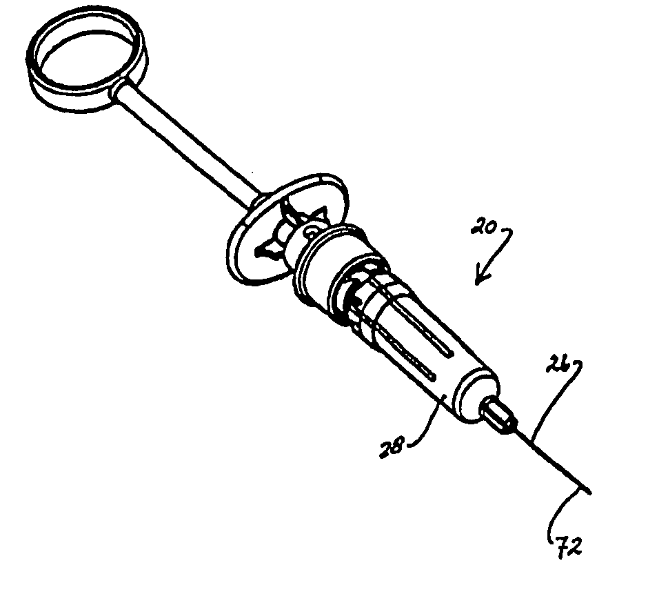
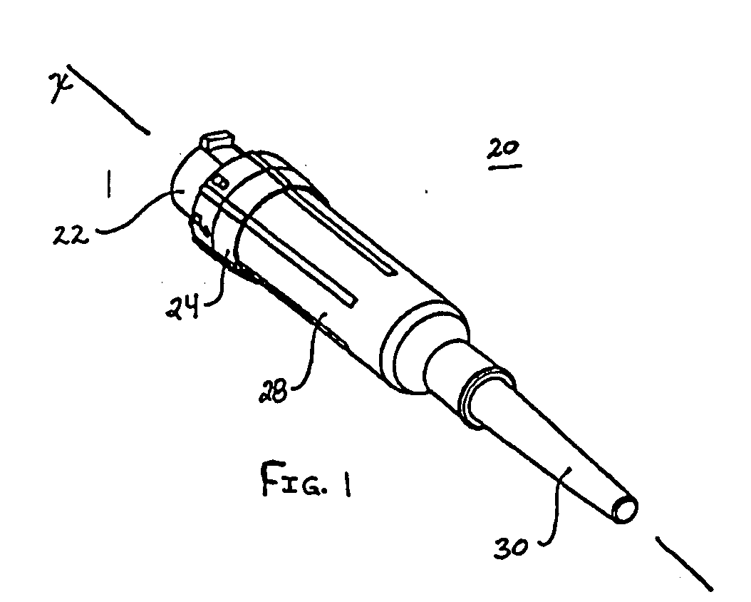
[0051] The exemplary embodiments of the safety needle apparatus and methods of operation disclosed are discussed in terms of medical needle assemblies for the administration of fluids, and more particularly, in terms of a dental safety needle apparatus that is easily employed to prevent hazardous exposure to a needle during use, transport and upon completion of a procedure to facilitate disposal thereof. It is contemplated that the needle may be shielded during use including storage, transport, fluid infusion and / or collection, subsequent thereto, etc. It is envisioned that the present disclosure, however, finds application to a wide variety of cannula needles and devices for the infusion of preventive medications, medicaments, therapeutics, etc. as well as injections employed during procedures relating to phlebotomy, orthopedic, digestive, intestinal, urinary, veterinary types, etc., to a subject. It is also envisioned that the present disclosure may be employed for collection of b...


PUM


Abstract

A safety needle apparatus having a needle is provided that includes a first cylinder extending from a proximal end to a distal end thereof and defining a longitudinal axis. The first cylinder further defines at least one longitudinal keyway in a side wall thereof and at least one keyslot disposed adjacent the distal end of the first cylinder. The keyslot is rotationally spaced apart from the at least one keyway relative to the longitudinal axis. The keyway includes a raised surface relative to and disposed adjacent the distal end of the first cylinder. A second cylinder is mounted for relative movement with the first cylinder and defines at least one radially projecting key adjacent a proximal end thereof. The key is configured for axial movement along the keyway such that the second cylinder is movable between an activated position, whereby the key is releasably engaged with a proximal end of the keyway to expose the needle, and a transport position, whereby the key is releasably disposed adjacent the distal end of the first cylinder via an interference engagement with the raised surface of the first cylinder to releasably enclose the needle within the second cylinder. The second cylinder is further movable from the transport position to a locked position, whereby the key is rotated relative to the first cylinder for fixed disposal within the keyslot to fixedly enclose the needle within the second cylinder.

Description

[0001] 1. Technical Field[0002] The present disclosure generally relates to the field of medical needle assemblies for the administration of fluids, and more particularly, to safety shields that prevent hazardous exposure to a needle during use and transport.[0003] 2. Description of the Related Art[0004] Problems associated with inadvertent needle sticks are well known in the art of fluid sampling, percutaneous medication injection and other medical procedures involving the use of medical needles. Significant attention is focused on health risks associated with hazardous needle exposure due to the contemporary sensitivity of exposure to AIDS, Hepatitis and other serious blood-borne pathogen exposures. These risks are some of the most prevalent occupational health hazards among healthcare professionals. These professionals are in danger of contracting such blood-borne pathogens from infected patients by inadvertent needle sticks from a contaminated needle employed during dental, medi...

Claims


Application Information

Patent Timeline
IPC IPC(8): A61M5/24A61M5/32
CPCA61M5/24A61M2005/3247A61M5/3272A61M5/3271
Inventor STEWART, BRADLEY M
Owner CARDINAL HEALTH IRELAND UNLTD
Learn More