Portable heat sealer

Inactive Publication Date: 2004-02-05
IDOLON TECH
View PDF22 Cites 23 Cited by
  • Summary
  • Abstract
  • Description
  • Claims
  • Application Information

AI Technical Summary

Benefits of technology

0009] Previous attempts to address the issue of uniform heating of the sealer bar have included improvements upon a sheathed type electrical heater which utilizes magnesium oxide insulation as described in U.S. Pat. No. 1,869,140, issued Jul. 26, 1932 to W. F. Gelinas. Another example of this is a rod type heating device consisting of a bent longitudinal element configured in a manner to provide uniform heat in the center of the element as described in U.S. Pat. No. 4,349,727, issued Sep. 14, 1982, to John W. Churchill. Various other configurations of the rod type-heating element ha

Problems solved by technology

However, imperfect seals occur due to non-uniform heating along the heated jaw.
While relatively inexpensive and relatively rapid in operation such method of sealing is not able to consistently produce strong liquid-tight hermetic seals.
However, such inferior sealing is not acceptable in other situations where the seal made by a heated wire has relatively little strength and may easily burst from internal pressure.
All such prior art devices, including heated sealer bars and heated wires, have been subject to heating problems in which the thermoplastic films can be either overheated or under heated causing imperfect seals as well as problems of non-uniform heating along the length of the seal due to variations in the pressure and temperature along the heated sealing bar.
This problem is particularly acute when a heated sealer bar is used to produce hermetic seals that are long and wide for thick, laminate, thermoplastic films.
If more heat than is necessary is used to cause bonding of the thermoplasti

Method used


Image

  • Portable heat sealer
  • Portable heat sealer
  • Portable heat sealer

Examples


Embodiment Construction

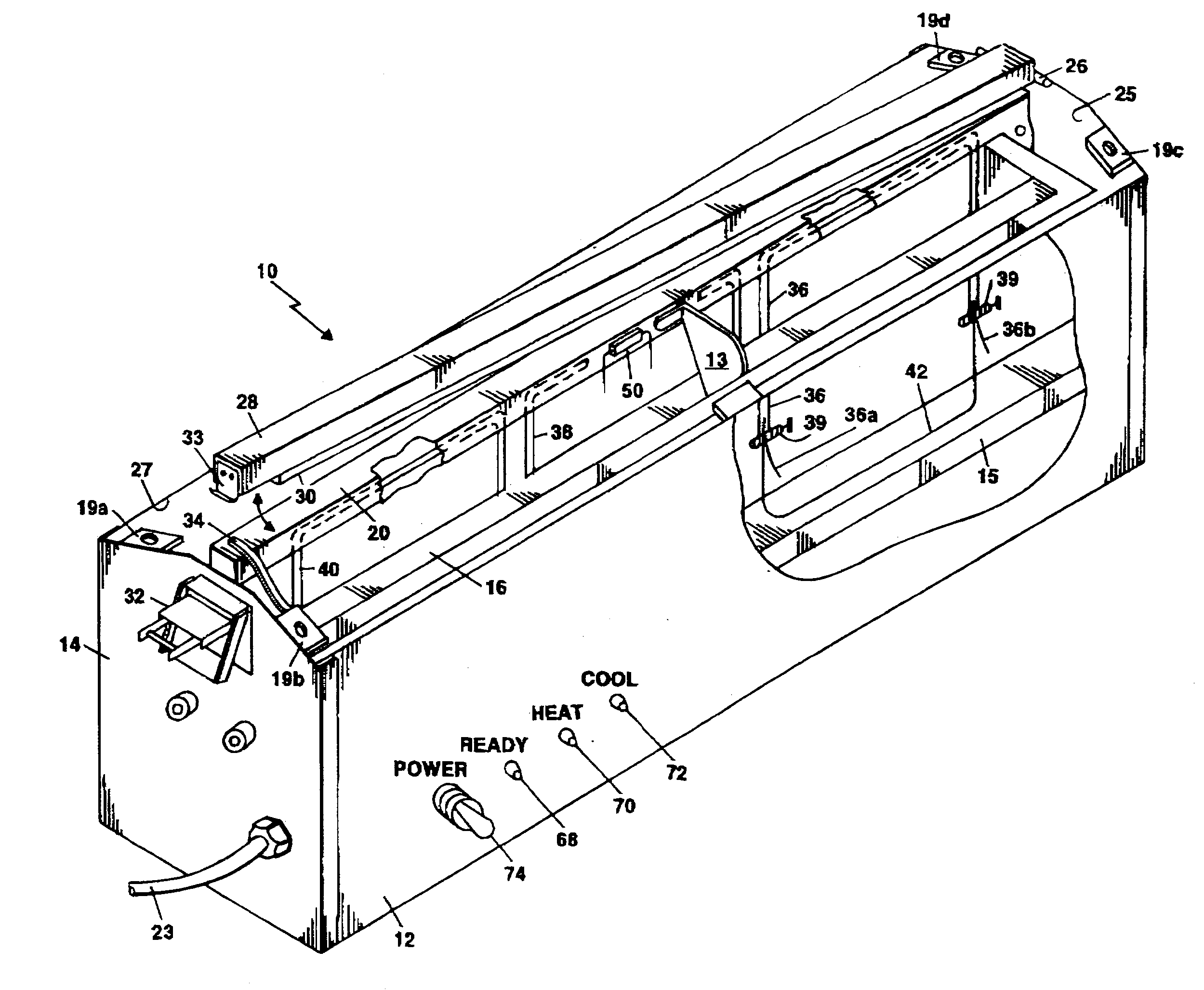
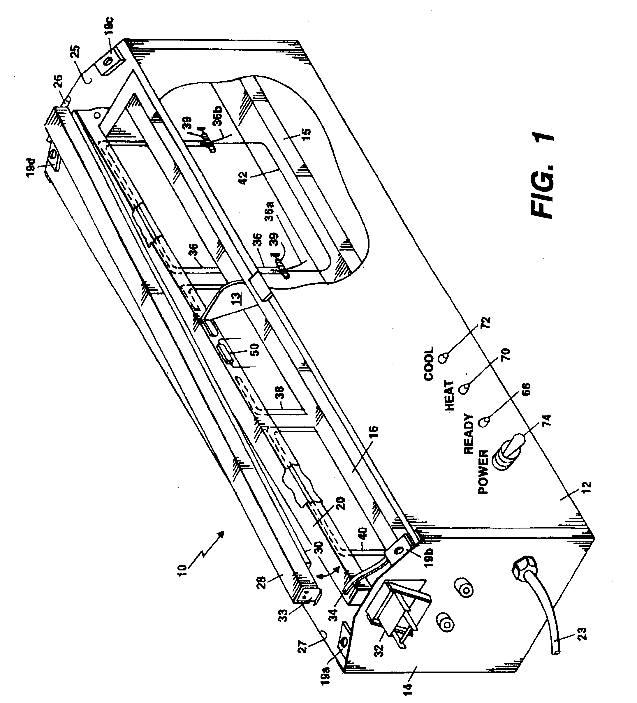
[0028] Referring to FIG. 1, a perspective view of a portable heat sealer 10 according to the invention is shown which is easily picked up and moved to different operating locations by an operator. An enclosure 11 for the heat sealer 10 comprises side panels 12, 27 and end panels 14, 25, a bottom panel (not shown) and two top panels (not shown). The top panels extend from end to end and mount on each side of a heated sealing bar 20. The top panels when attached to the enclosure 11 rest on tabs 19a, 19b, 19c and 19d, and the top panels are secured to each of the tabs 19a-19d by screws.

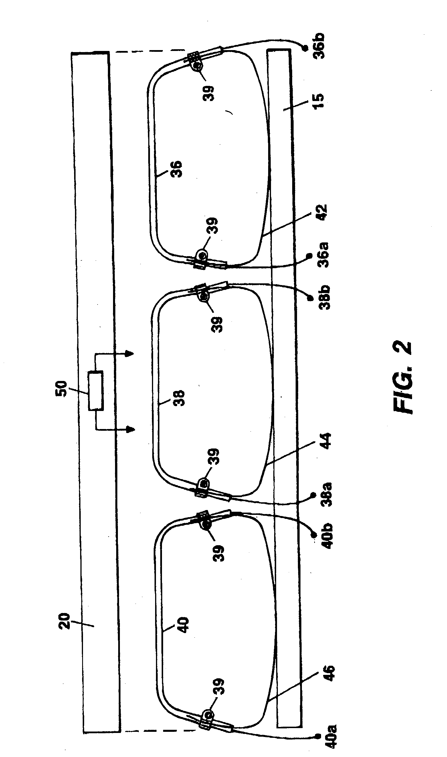
[0029] Referring to FIG. 1 and FIG. 2, FIG. 2 is a side elevational view of three adjacent segmented heating elements 36, 38, 40 for providing heat to the heated sealing bar 20 within the portable heat sealer 10. The segmented heating elements 36, 38, 40 are mounted underneath the heated sealing bar 20 and in a line adjacent to each other. Tension springs 42, 44, 46 are attached to each of the heating el...


PUM

PropertyMeasurementUnit
Temperatureaaaaaaaaaa
Pressureaaaaaaaaaa
Poweraaaaaaaaaa

Abstract

A portable heat sealer for sealing heavy grade thermoplastic films comprises a plurality of adjacent, segmented heating elements positioned along the underside of a heated sealing bar. The segmented heating elements are under the control of a microprocessor for controlling the energy applied to the heated sealing bar to avoid the formation of hot spots and to obtain a strong seal. Each heating element is maintained in firm contact with the heated sealing bar by means of a tension spring. A thermoplastic film bag is placed on the heated sealing bar and a movable sealer jaw is lowered on top of the bag. A jaw switch is activated by the sealer jaw which turns-on power to the heat sealer. A latch 32 attaches to a clip on the end of the sealer jaws and secures the sealer jaw in place. Pilot lights are provided to indicate to an operator the cycles of "ready", "heat" and "cool".

Description

[0001] This is a Nonprovisional patent application claiming priority of Provisional Application for Patent Serial No. 60 / 375,563, filed Apr. 25, 2002, and it is incorporated herein by reference.[0002] 1. Field of the Invention[0003] This invention relates to a heat sealing apparatus for sealing thermoplastic films, and in particular to a portable heat sealer having a plurality of adjacent segmented heating elements, positioned along the underside of a heated sealing bar, which operates under microprocessor control.[0004] 2. Description of Related Art[0005] Thermoplastic films are conventionally sealed by heat applied in a number of ways including hot wires, ultrasonically vibrated heads, and radiant energy. Such sealing devices normally utilize opposed jaw members with one of the jaw members being heated and the other jaw member provided with a resilient facing. Generally the heated jaw of the sealer consists of an aluminum bar with an internal heating element which is known in the ...

Claims


Application Information

Patent Timeline
IPC IPC(8): B29C65/00B29C65/22B65B51/14
CPCB29C66/1122B29C66/43121B29C66/80B29C66/81457B29C66/861B29C66/91212B29C66/91231B29C66/91421B29C66/949B29C66/96B29K2101/12B65B51/148B29C66/43B29C66/9241B29C65/223B29C66/8324B29C65/247B29C65/229B29C66/91651B29C66/91641B29C66/91653B29C66/81871B29C66/91213B29C66/944B29C66/961B29C65/00B29C65/30B29C66/0342B29C66/73921B29C66/8122B29C66/81241B29C66/81261B29C66/8161B29C66/8221B29C66/8286B29C66/8618B29C66/9441B29K2821/00
Inventor HOVORKA, GEORGE B.
Owner IDOLON TECH
Why Eureka
Try Eureka