Plate-shaped cover material

a plate-shaped, cover material technology, applied in snow traps, building components, yarn, etc., can solve the problems of material sliding, material slipping, and surface not suitable for painting

Inactive Publication Date: 2004-02-12
MEIER POUL ERNST
View PDF42 Cites 11 Cited by
  • Summary
  • Abstract
  • Description
  • Claims
  • Application Information

AI Technical Summary

Benefits of technology

0007] The object of the invention is to provide a new and improved cover material of the above type, s

Problems solved by technology

At high temperatures, eg on a hot summer's day, the wax may escape from the polyisobutylene substrate and thus ruin the bonding to the base, whereby the material may slide.
Furthermore, the surface is not suitable for being painted over.
These additives hampers the adhesiveness of the material such that long-term adhesion is dif

Method used


Image

  • Plate-shaped cover material
  • Plate-shaped cover material
  • Plate-shaped cover material

Examples


Embodiment Construction

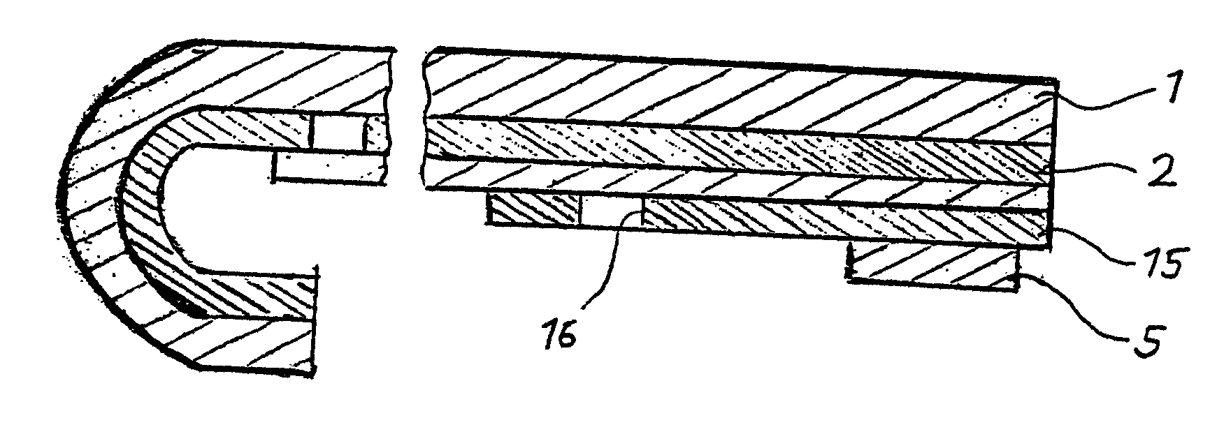
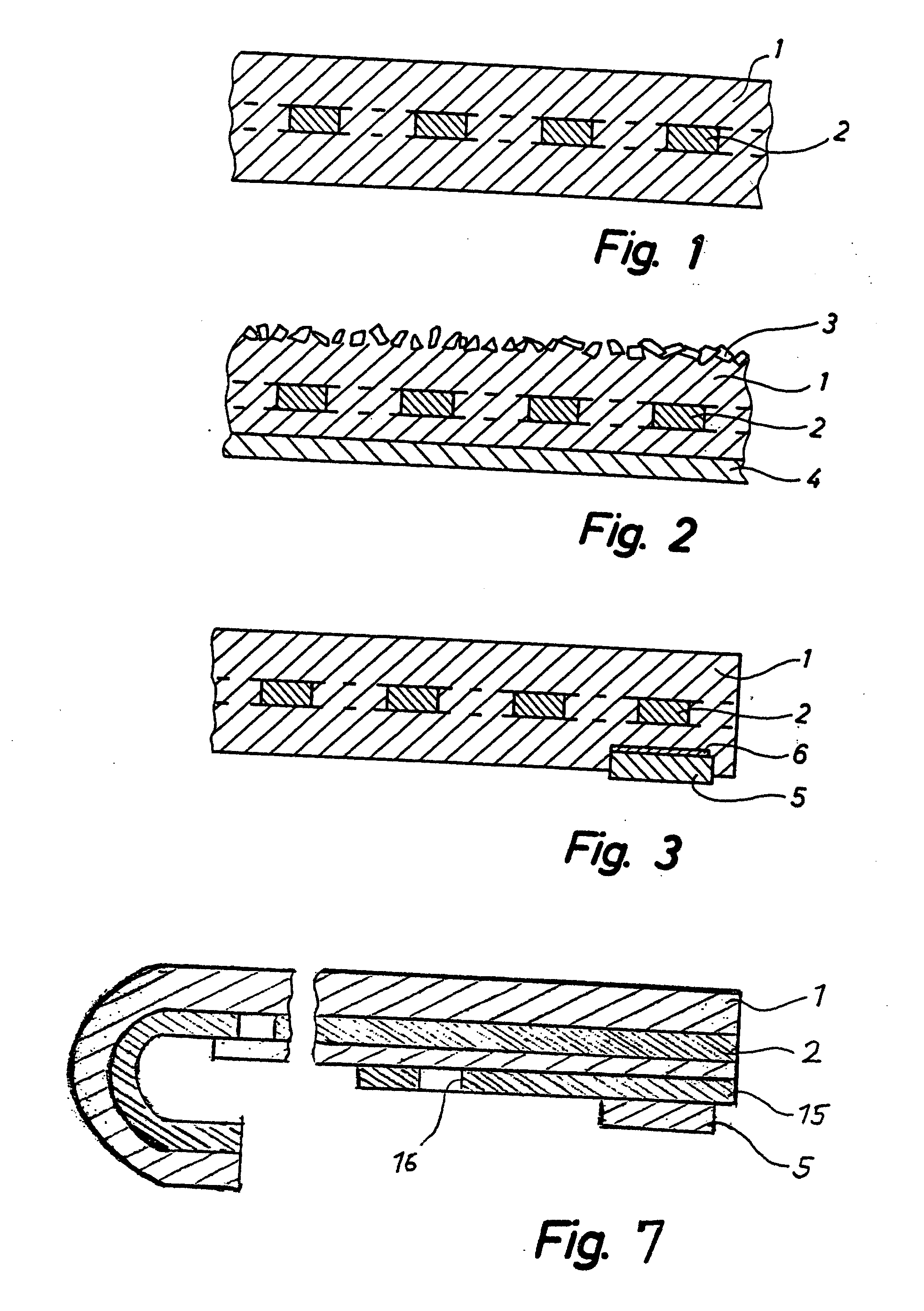
[0041] The embodiment shown in FIG. 1 simply consists of an expanded metal grid 2 of aluminium and an elastomeric layer 1 comprising MS polymer. By means of a suitable heat treatment at about 300.degree. C. the expanded metal grid 2 has been recrystallized to obtain a high plastic deformability. The MS polymer of the elastomer may be any MS polymer possessing the desired properties. Casco Bygfuge S20 containing 1-5% of vinyltrimethoxysilane, 10-30% of polyoxypropylene (MS polymer) and 30-60% of calcium carbonate is used in the embodiment shown. In its cured state this compound has a Shore A hardness of 20-30. The aluminium expanded metal grid has a mesh size of 10.times.5 mm, a rib width of 1.5 mm and a rib thickness of 0.9 mm. The thickness of the cover material per se, ie of the elastomeric layer, is about 3 mm.

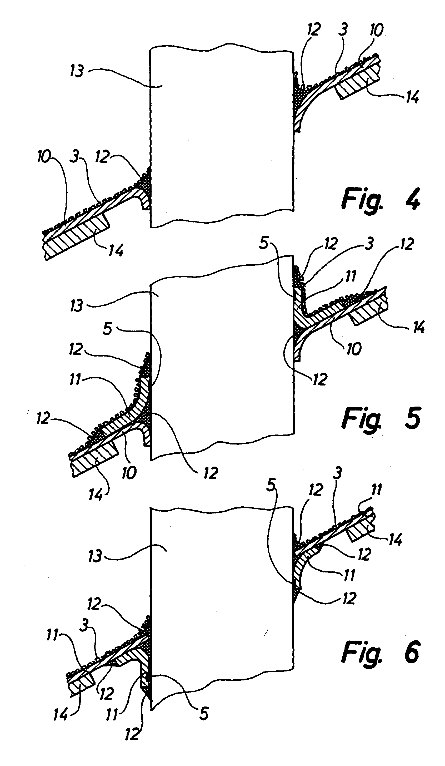
[0042] The embodiment of the cover material according to the invention shown in FIG. 2 is provided with a UV-protecting layer 3 of ground slate. The slate has paint compati...


PUM

PropertyMeasurementUnit
Percent by massaaaaaaaaaa

Abstract

Plate-shaped cover material comprising an elastomeric layer and a plastically deformable metal mesh or metal plate, the elastomeric layer consisting of a glue or joint sealant cured to an elastomer and having strong adhesion to the metal mesh or the metal plate.

Description

[0001] The invention relates to a plate-shaped cover material comprising an elastomeric layer and a plastically deformable metal mesh or metal plate. Such cover materials are particularly used for flashing roof lead-ins, such as chimneys, skylights, air ducts, attics and the like. The cover material is further suitable for preformed, plastically deformable flashing sections and the like building members.[0002] DE 3642063 discloses a cover material according to the preamble of claim 1, and wherein the elastomeric layer is formed of a non-tacky polyisobutylene substrate (PIB). The cover material is provided with an adhesive layer for being sealed to a base, eg a roof, in connection with a roof lead-in. Wax is added so as to protect the polyisobutylene substrate against ozone. At high temperatures, eg on a hot summer's day, the wax may escape from the polyisobutylene substrate and thus ruin the bonding to the base, whereby the material may slide. Furthermore, the surface is not suitabl...

Claims


Application Information

Patent Timeline
IPC IPC(8): B32B15/06E04D13/14E04D13/147E04F13/06
CPCB32B15/06E04D13/14Y10T428/2962E04F13/06E04D13/1476
Inventor MEIER
Owner MEIER POUL ERNST
Why Eureka
Try Eureka