Fuel delivery system for an internal combustion engine

a fuel delivery system and internal combustion engine technology, applied in the direction of electric control, combustion-air/fuel-air treatment, speed sensing governors, etc., can solve the problem that the idle speed control valve increases the overall cost of the fuel delivery system, the manual action of the throttle is insufficient by itself and the idle speed control valve is insufficient to control the air flow rate during idle and/or cold start engine operation conditions, etc. problem, to achieve the effect of enhancing th

Inactive Publication Date: 2004-02-12
HITACHI LTD
View PDF48 Cites 36 Cited by
  • Summary
  • Abstract
  • Description
  • Claims
  • Application Information

AI Technical Summary

Benefits of technology

0017] Optionally, a cold start fuel injector is associated with the bypass gas flow passageway. The ECU controls the actuation of the cold start fuel injector to inject fuel into the bypass gas flow ...

Problems solved by technology

While the previously known manually actuated throttles for internal combustion engines have operated satisfactorily during high engine RPM operating conditions, such manually controlled throttles have been inadequate by themselves to control the air flow rate to the internal combustion chambers of the engine during an idle and/or cold start operating condition.
The inability of the manually actuated throttles to control the air flow rate during an idle and/or cold start engine operating condition arises primarily through government emission standards which require increasingly lower levels of noxious emissions from the engine during all engine operating con...

Method used


Image

  • Fuel delivery system for an internal combustion engine
  • Fuel delivery system for an internal combustion engine
  • Fuel delivery system for an internal combustion engine

Examples


Embodiment Construction

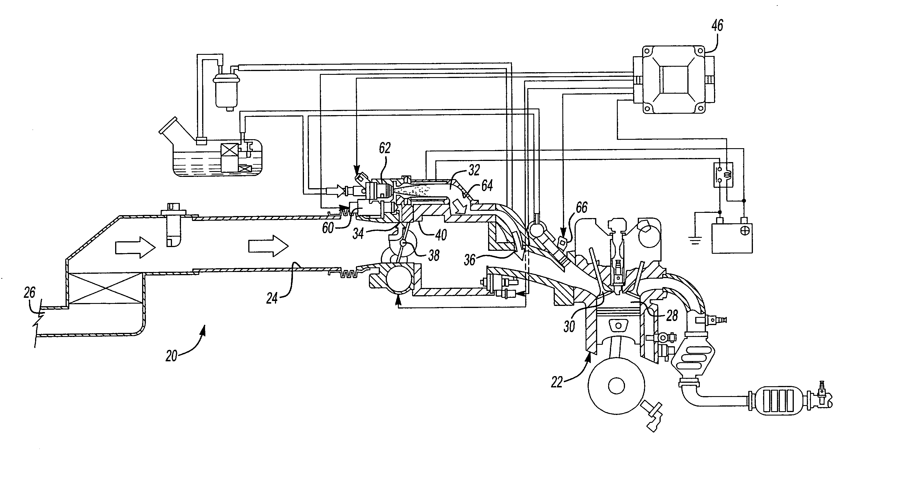
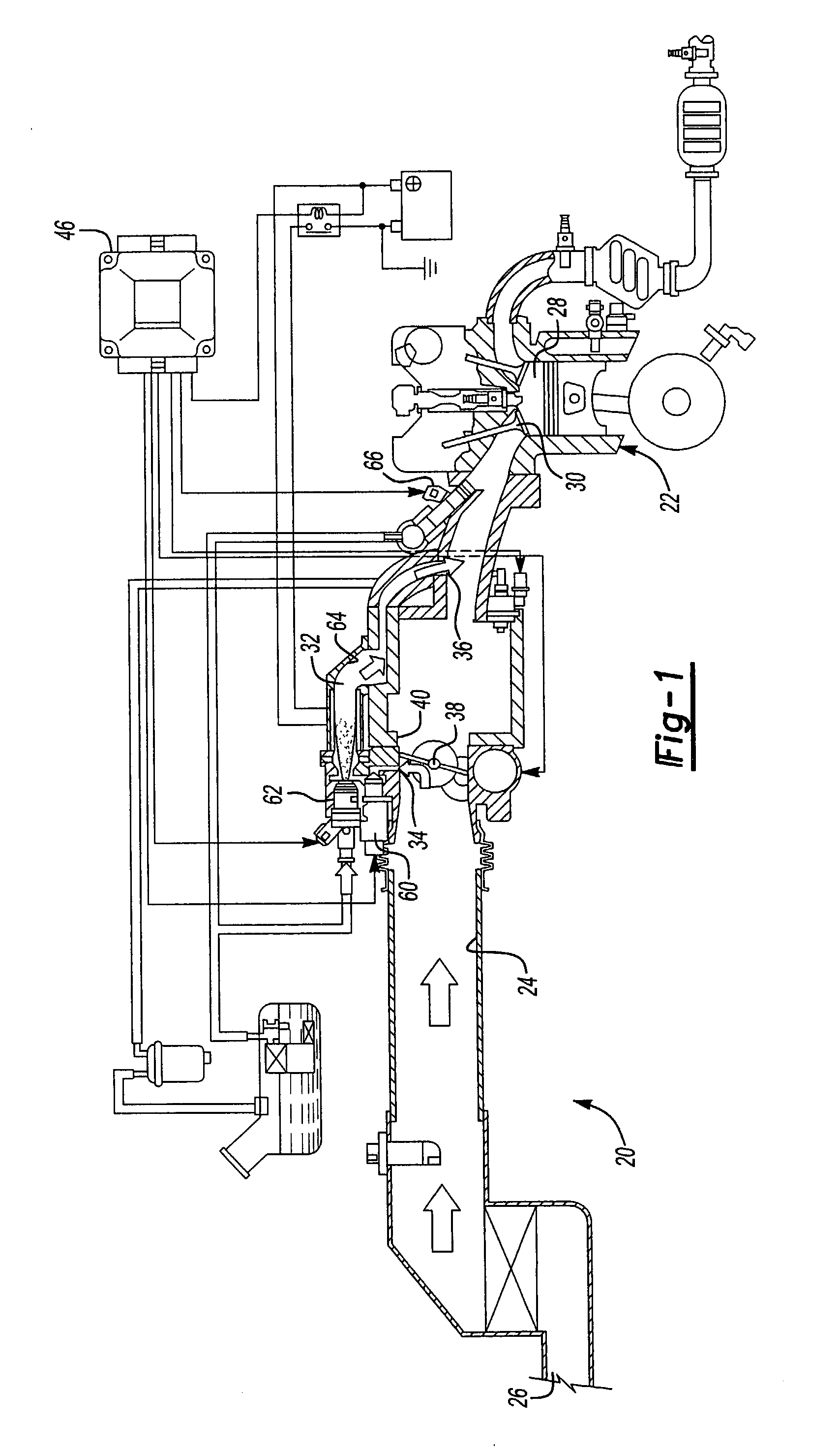
[0034] With reference first to FIG. 1, a first preferred embodiment of the fuel delivery system 20 is there shown for use with an internal combustion engine 22 (illustrated only diagrammatically). The internal combustion engine 22 includes an intake manifold 24 having an intake end 26 through which air is inducted. The intake manifold 24, in the conventional fashion, fluidly connects the intake 26 to a combustion chamber 28 of the internal combustion engine 22 via an intake valve 30.

[0035] Still referring to FIG. 1, a bypass gas flow passageway 32 has an inlet 34 open to the intake manifold 24. Similarly, the bypass passageway 32 has an outlet 36 which is open to the intake manifold 24 downstream from the inlet 34.

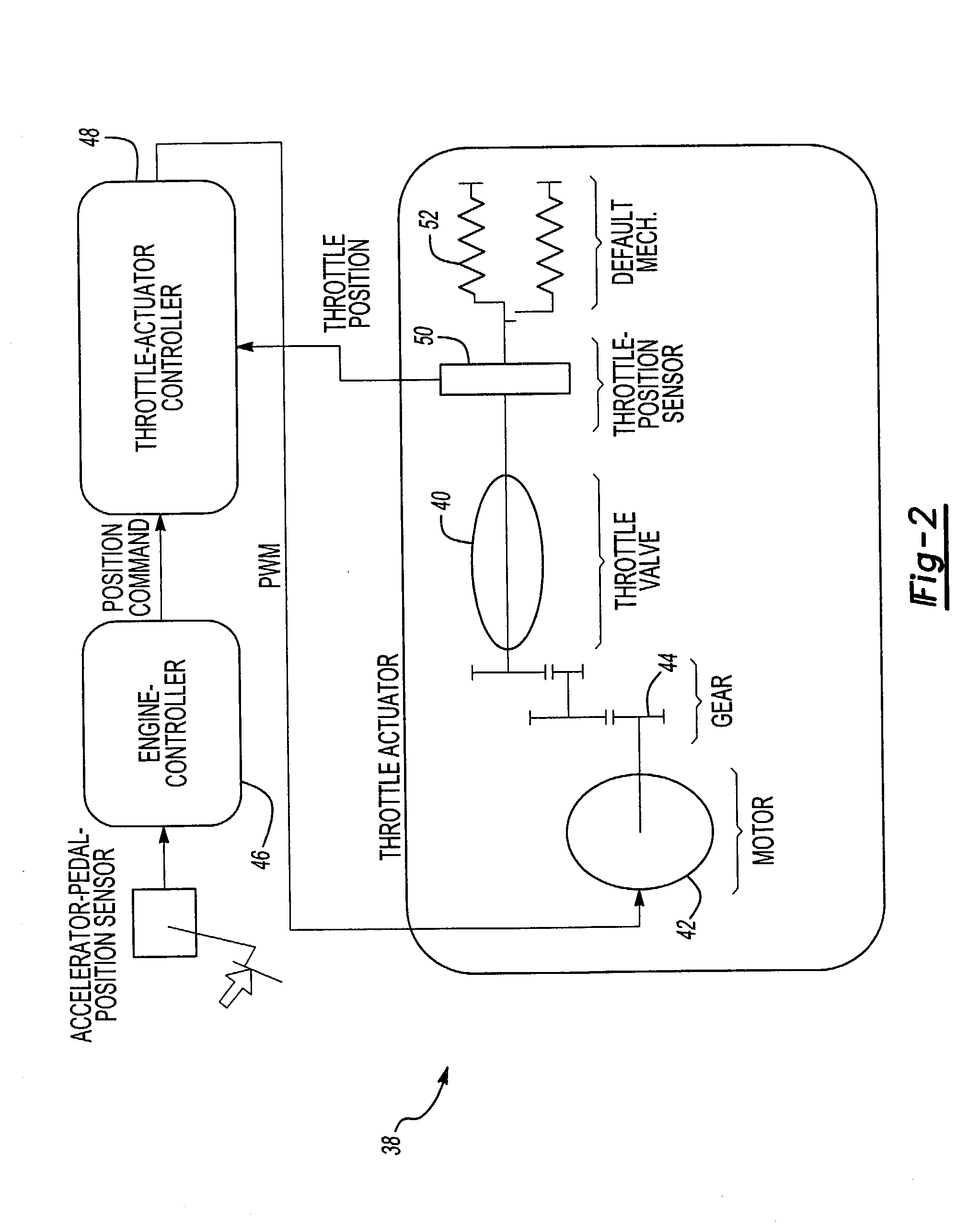
[0036] An electronically controlled throttle valve 38 is operatively positioned within the intake manifold 24. The throttle valve 38 is a linear valve movable between an open position and a closed position (illustrated in FIG. 1) to control the air flow through the intake ...


PUM


Abstract

A fuel delivery system for an internal combustion engine of the type having an intake manifold selectively fluidly connected to a combustion chamber and a bypass gas flow passageway having an inlet open to the intake manifold and an outlet open to the intake manifold downstream for the inlet is disclosed. The system includes an electronically controlled throttle valve operatively disposed in the intake manifold and movable between an open and a closed position to control air flow through the intake manifold. An idle speed control valve is operatively disposed within the bypass gas flow passageway, and the idle speed control valve is also movable between an open and a closed position to control air flow through the bypass gas flow passageway. A control system controls the actuation of both the throttle valve and idle speed control valve to control the delivery of a combustible charge to the internal combustion engine to maximize engine efficiency and minimize noxious emissions. Optionally, a cold start fuel injector is disposed within the bypass gas flow passageway to provide the fuel charge to the engine during a cold start condition. In an alternate form of the invention, two electronically controlled throttle valves are disposed within the intake manifold to control both the air flow through the intake manifold as well as the air flow through the bypass gas flow passageway.

Description

[0001] I. Field of the Invention[0002] The present invention relates generally to a fuel delivery system for an internal combustion engine.[0003] II. Description of the Prior Art[0004] In conventional gasoline fueled internal combustion engines of the type used in the automotive industry, a manually actuated throttle body is fluidly disposed in series with the intake manifold upstream from the engine combustion chamber(s). This manually controlled throttle is mechanically linked to the accelerator pedal in the automotive vehicle such that depression and release of the accelerator pedal respectively opens and closes the throttle plate of the throttle valve. The opening and closure of the throttle plate within the intake manifold, of course, controls the mass air flow rate through the intake manifold.[0005] While the previously known manually actuated throttles for internal combustion engines have operated satisfactorily during high engine RPM operating conditions, such manually contr...

Claims


Application Information

Patent Timeline
IPC IPC(8): F02D9/02F02M31/135F02D11/10F02D21/08F02D31/00F02D41/06F02M25/07F02M37/00F02M53/06F02M69/00F02M69/32
CPCF02D11/105F02D31/005F02D2200/602F02D2011/102F02D2200/0404F02D41/064
Inventor HUNT, FRANK WARRENOHO, SHIGERUMIYAJIMA, AYUMU
Owner HITACHI LTD
Why Eureka
Try Eureka