
Components and methods for use in electro-optic displays

Active Publication Date: 2004-02-12
E INK CORPORATION
View PDF99 Cites 369 Cited by
  • Summary
  • Abstract
  • Description
  • Claims
  • Application Information

AI Technical Summary

Benefits of technology

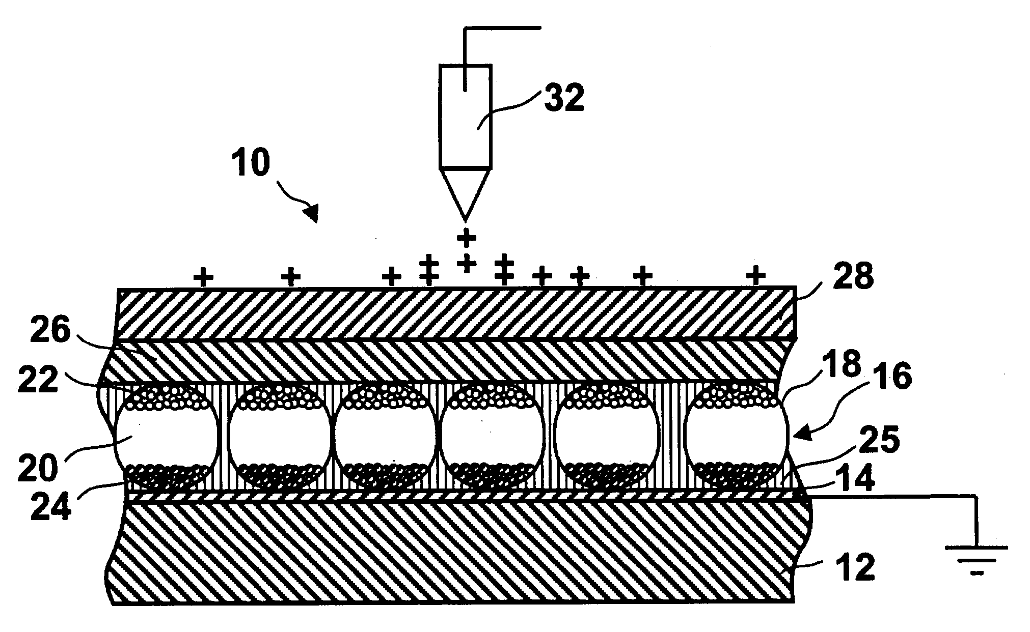
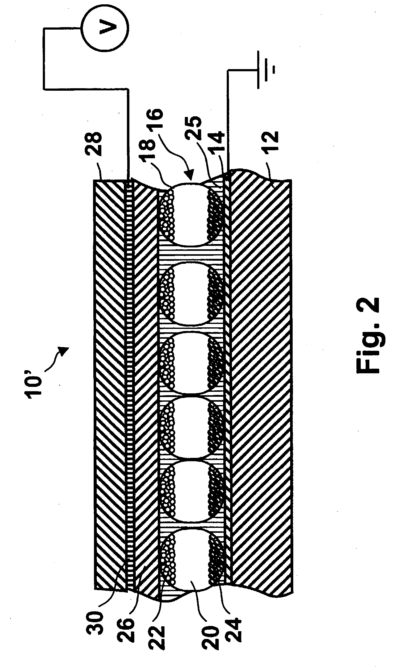
[0066] In another aspect, this invention provides a (sealed) electro-optic display comprising a backplane comprising at least one pixel electrode; a layer of a solid electro-optic medium disposed adjacent the pixel electrode; a light-transmissive electrode disposed on the opposed side of the electro-optic medium from the backplane; a protective and / or barrier layer disposed on the opposed side of the light-transmissive electrode from the electro-optic medium; and a sealing material for preventing ingress of material from the environment into the electro-optic medium, the sealing material being disposed along at least part of the periphery of the layer of electro-optic medium and extending from the backplane of the protective and / or barrier layer.

Problems solved by technology

Nevertheless, problems with the long-term image quality of these displays have prevented their widespread usage.
For example, particles that make up electrophoretic displays tend to settle, resulting in inadequate service-life for these displays.
However, the methods used for assembling LCD's cannot be used with solid electro-optic displays.
This LCD assembly process cannot readily be transferred to solid electro-optic displays.
As discussed in the aforementioned U.S. Pat. No. 6,312,304, the manufacture of solid electro-optic displays also presents problems in that the optical components (the electro-optic medium) and the electronic components (in the backplane) have differing performance criteria.
Therefore, a process for manufacturing an optical component may not be ideal for manufacturing an electronic component, and vice versa.
The processing temperature can be in the range from about 300 .ANG..degree. C. to about 600 .ANG..degree. C. Subjecting many optical components to such high temperatures, however, can be harmful to the optical components by degrading the electro-optic medium chemically or by causing mechanical damage.
Electro-optic displays are often costly; for example, the cost of the color LCD found in a portable computer is typically a substantial fraction of the entire cost of the computer.
However, such equipment is costly and the areas of electro-optic media presently sold may be insufficient to justify dedicated equipment, so that it may typically be necessary to transport the coated medium from a commercial coating plant to the plant used for final assembly of electro-optic displays without damage to the relatively fragile layer of electro-optic medium.
One practical problem in the manufacture of electro-optic displays, especially flexible displays, is sealing the display to prevent ingress of materials from the environment (and / or, in some cases, egress of components of the electro-optic medium).
For example, organic light emitting diodes (which may be useful as the electro-optic medium of a display) are notoriously sensitive to damage caused in ingress of atmospheric moisture, and some particle-based electrophoretic media have also been shown to have some sensitivity to moisture.

Method used


Image

  • Components and methods for use in electro-optic displays
  • Components and methods for use in electro-optic displays
  • Components and methods for use in electro-optic displays

Examples


Embodiment Construction

was deposited on a release sheet, dried, and overcoated with an aqueous urethane binder (NeoRez R-9320, available from NeoResins, 730 Main Street, Wilmington Mass. 01887), which served to planarize the layer of capsules and form an adhesive layer. After drying the adhesive layer, the combined capsule layer and adhesive layer could be peeled away from the substrate as a self-supporting film.

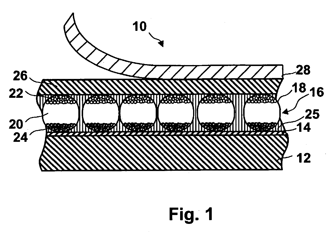
[0104] The front plane laminate of the present invention is well adapted for mass production. For example, a roll of a commercial metallized plastic film may be converted to the front plane laminate by a roll-to-roll coating processing using conventional commercial coating equipment. The metallized plastic film is first coated with a slurry of capsules in binder, as described in the aforementioned application Ser. No. 10 / 063,803, and this capsule layer is dried. A layer of adhesive, for example the aforementioned aqueous urethane resin NeoRez R-9320, is then coated over the capsule layer and dried...


PUM


Abstract

A front plane laminate useful in the manufacture of electro-optic displays comprises, in order, a light-transmissive electrically-conductive layer, a layer of an electro-optic medium in electrical contact with the electrically-conductive layer, an adhesive layer and a release sheet. This front plane laminate can be prepared as a continuous web, cut to size, the release sheet removed and the laminate laminated to a backplane to form a display. Methods for providing conductive vias through the electro-optic medium and for testing the front plane laminate are also described.

Description

[0001] This application claims priority from copending application Ser. No. 60 / 319,300, filed Jun. 10, 2002, and from copending application Ser. No. 60 / 320,186, filed May 12, 2003. The entire contents of all United States patents and published applications mentioned above and below are herein incorporated by reference.BACKGROUND OF INVENTION[0002] The present invention relates to processes and components for forming electro-optic displays. More specifically, this invention relates to such processes and components for forming electro-optic displays containing an electro-optic medium which is a solid (such displays may hereinafter for convenience be referred to as "solid electro-optic displays"), in the sense that the electro-optic medium has solid external surfaces, although the medium may, and often does, have internal liquid-or gas-filled spaces, and to methods for assembling displays using such an electro-optic medium. Thus, the term "solid electro-optic displays" includes encapsu...

Claims


Application Information

Patent Timeline
IPC IPC(8): B31B50/62G02F1/167G02F1/1675G09F9/00
CPCG02F1/133377G02F1/1339G02F1/1508G02F1/167G02F1/172G02F2203/69Y10T156/10B32B37/12B32B37/18B32B2307/202B32B2457/20Y10T428/1476B05D7/5483G02F2202/28G02F1/1681G02F1/1675G02F1/1309G02F2001/1678G02B1/14
Inventor LECAIN, RICHARD D.KNAIAN, ARA N.O'NEIL, STEVEN J.DUTHALER, GREGG M.DANNER, GUY M.ZEHNER, ROBERT W.GOENAGA, ALBERTODAVIS, BENJAMIN MAXCHAN, RANDOLPH W.ALBERT, JONATHAN D.CROSSLEY, GLEN
Owner E INK CORPORATION
Learn More