[0019] In one aspect of the present embodiment, the rotary hub may be provided with a fixing section that protrudes in the axial direction from an end surface in the axial direction of the rotary hub, which fixes the hub mounting section of the circular ring-shaped member through plastic deformation. The inner circumference surface of the fixing section may be formed as a regulating surface that positions the hub mounting section of the circular ring-shaped member. As a result, the hub mounting section can be readily mounted on the rotary hub with high precision due to the positioning regulating surface of the fixing section; and this results in a firmly fixed state between the hub mounting section and the rotary hub through the plastic deformation of the fixing section.
[0020] The dynamic pressure bearing motor may be further provided with a circumferential wall section that collects a
coating sealer for the plastically deformed fixing section formed on the rotary hub outer side in the radial direction of the fixing section. As a result,
contamination that may be caused by plastically deforming the fixing section can be favorably prevented and the lubricating fluid can be favorably prevented from flowing outside the fixing section by the
coating sealer.
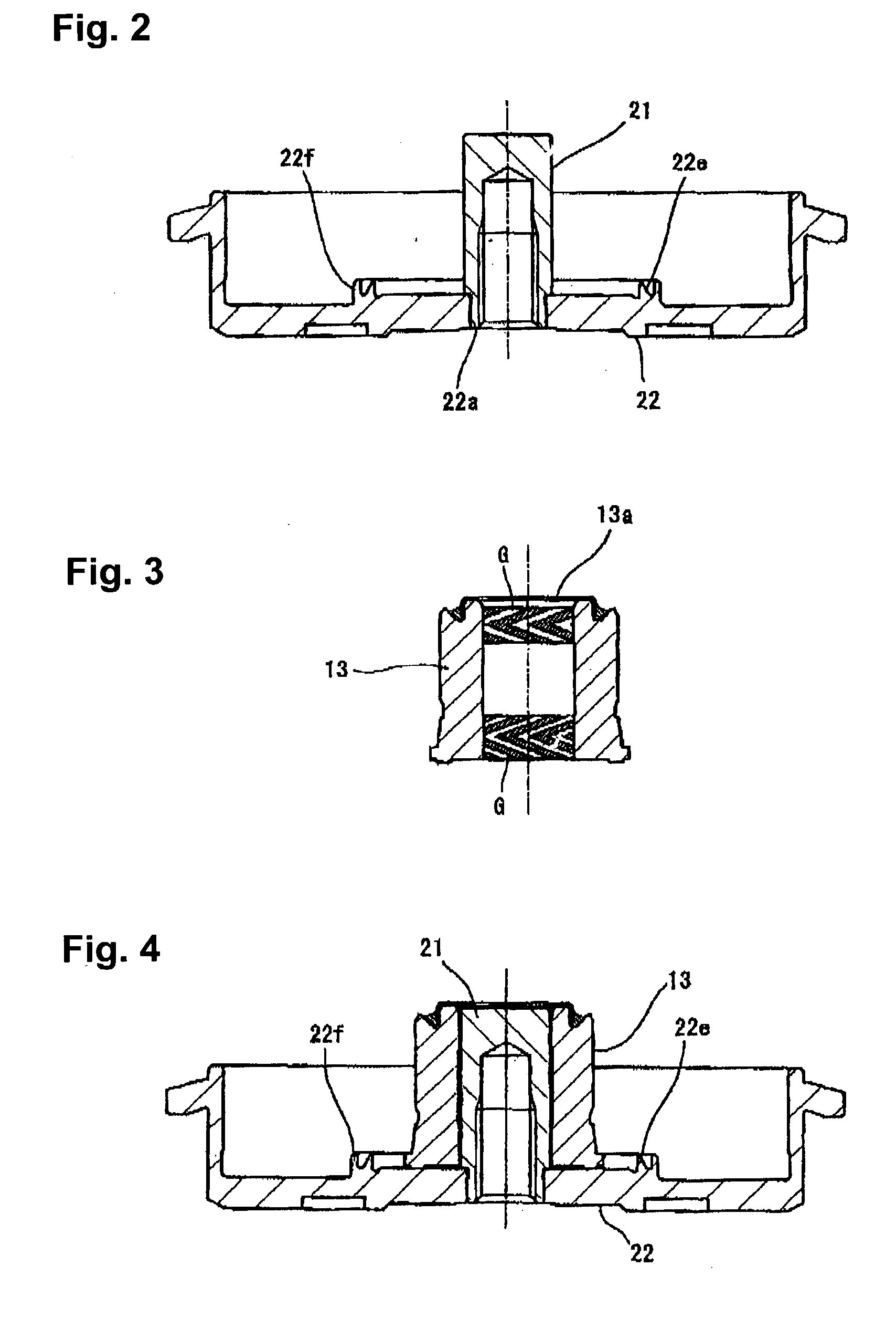
[0021] In the dynamic pressure bearing motor, the fluid sealing section may have a capillary sealing structure whose gap dimension gradually enlarges towards an opening of the fluid sealing section, and both of the outer circumference surface of the dynamic pressure bearing sleeve and the inner circumference surface of the main body section of the circular ring-shaped member, which together form the fluid sealing section, may have a tapered surface that slopes inward in the radial direction towards the opening of the fluid sealing section, such that the center axial line of the fluid sealing section slopes inward in the radial direction towards the opening. As a result, the centrifuigal force during rotation, in addition to the inherent capillary sealing effect of the fluid sealing section, works to push inward the lubricating fluid inside the fluid sealing section, which results in an substantially favorable sealing effect.
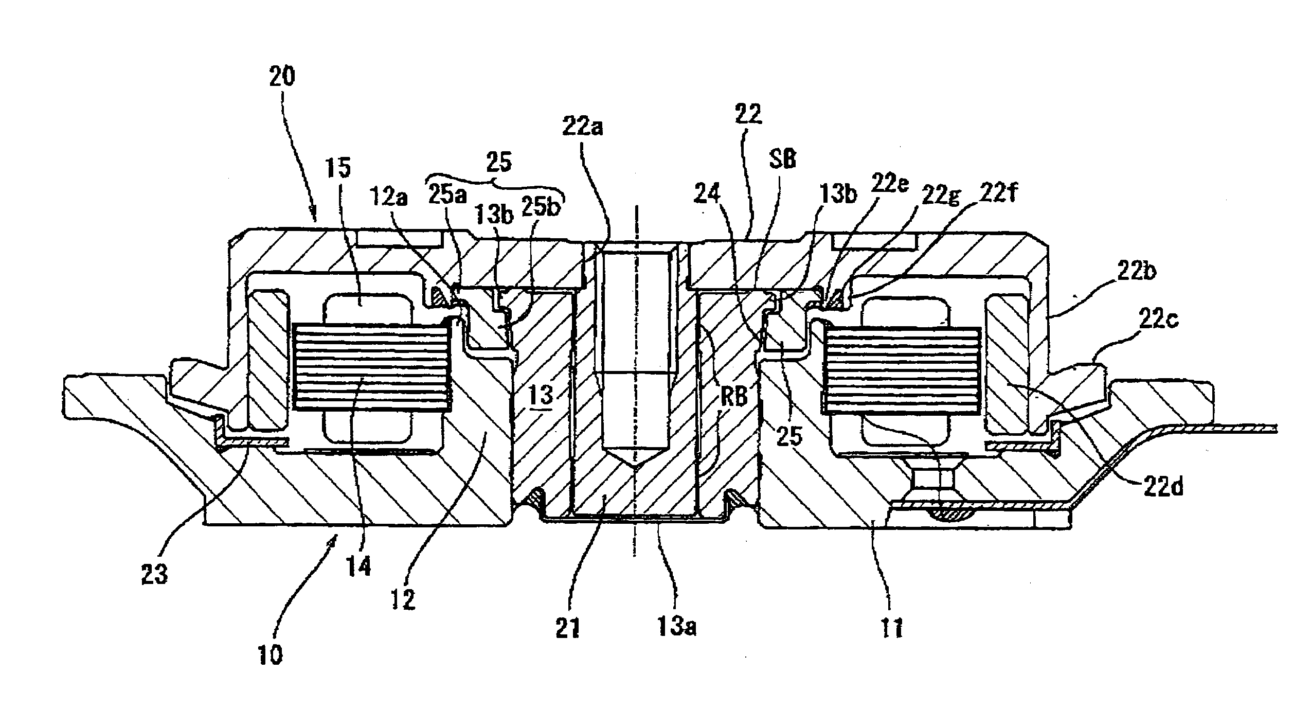
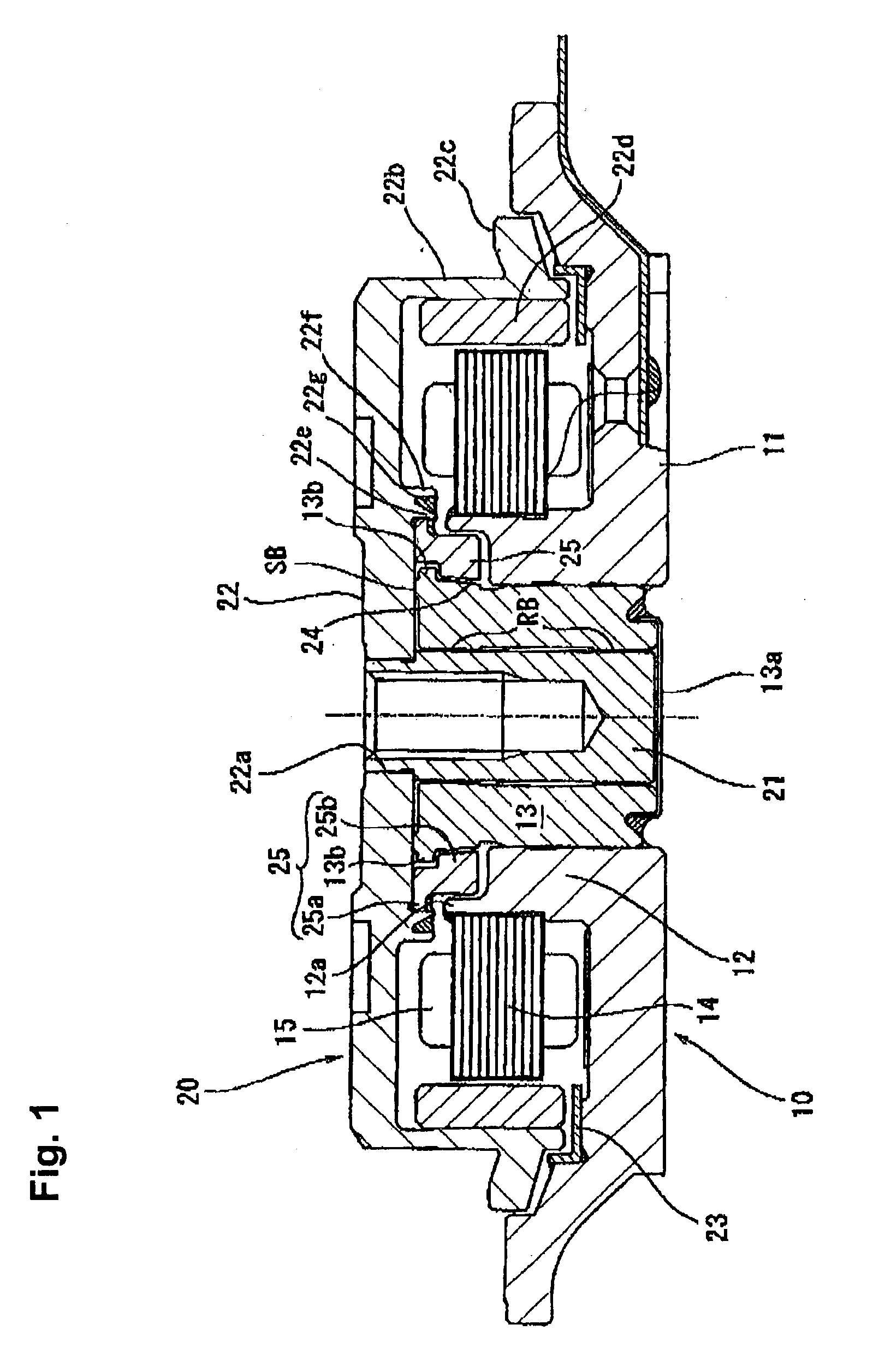
[0016] In accordance with one embodiment of the present invention, a dynamic pressure bearing motor is equipped with a dynamic pressure bearing sleeve for supporting a rotary shaft by a dynamic pressure; a rotary hub coupled to the rotary shaft; a thrust dynamic pressure bearing section formed between the dynamic pressure bearing sleeve and the rotary hub; and a circular ring-shaped member that is placed to surround an outer circumference surface of the dynamic pressure bearing sleeve, and has a hub mounting section joined to an end surface of the rotary hub in a region radially outside of the thrust dynamic pressure bearing section and a main body section that inwardly protrudes from the hub mounting section. A fluid sealing section that prevents a lubricating fluid inside the thrust dynamic pressure bearing section from flowing outside is formed between the hub mounting section and an outer circumference surface of the dynamic pressure bearing sleeve, wherein the fluid sealing section is defined by a gap in the radial direction formed continuously from the thrust dynamic pressure bearing section. The dynamic pressure bearing sleeve includes a fallout stopper flange section that protrudes outward in the radial direction and opposes in the axial direction the main body section of the circular ring-shaped member to prevent the circular ring-shaped member from falling out in the axial direction. The inner circumference surface of the hub mounting section is positioned to oppose in the radial direction the outer circumference surface of the fallout stopper flange section of the dynamic pressure bearing sleeve.
[0024] As a result, the length of a holder member that holds a stator core can be sufficiently extended in the axial direction, and the height in the axial direction of the stator core holding section of the holder member can be extended to a position in the vicinity of the hub mounting section of the circular ring-shaped member. This results in sufficient joining force for the stator core and in a favorable control of the magnetic vibration of the stator core.
[0025] In accordance with another embodiment of the present invention, a dynamic pressure bearing motor is equipped with a rotating member that is rotatively driven in a unitary fashion with a rotary shaft; a dynamic pressure bearing member that rotatively supports the rotary shaft by dynamic pressure; and a thrust dynamic pressure bearing provided in a region where an end surface in the axial direction of the dynamic pressure bearing member and an end surface in the axial direction of the rotating member oppose each other in the axial direction. The rotating member includes a rotary hub that is made of an aluminum material and has a disk mounting section, and a thrust plate that is provided on the rotary hub and is made of an iron material and makes up a part of the thrust dynamic pressure bearing. As a result, wear on the rotary hub is controlled and the life of the dynamic pressure bearing can be extended, even when the hub and the dynamic pressure bearing member come into contact in start and stop operations.
[0029] In another aspect of the present invention, the rotary shaft can be fitted in a unitary fashion on the inner circumference side of the thrust plate and the rotating member can be mounted in a unitary fashion on the outer circumference side of the thrust plate. With such a structure, the
bonding strength between the hub made of an aluminum material and the rotary shaft can be increased.
