
Underdrain system

a technology of underdrain system and underdrain tube, which is applied in the direction of cartridge filter, filtration separation, separation process, etc., can solve the problems of significant problems with the operation of the filter, undue wear on the walls of the depression, and achieve the effect of preparing to retrofit a false bottom underdrain tub

Inactive Publication Date: 2004-02-19
RG DELAWARE
View PDF11 Cites 17 Cited by
  • Summary
  • Abstract
  • Description
  • Claims
  • Application Information

AI Technical Summary

Benefits of technology

The solution provides a cost-effective and efficient fluid distribution system that reduces operational issues and installation complexity, ensuring thorough fluid distribution and easy maintenance of the underdrain system.

Problems solved by technology

The porcelain balls are expensive and time-consuming to install.
This spinning can cause undue wear on the walls of the depressions.
This can lead to significant problems with the operation of the filter.
This underdrain system suffers from similar drawbacks to the monolithic false bottom underdrain systems.
However, this pyramidal shaped liner formed from plastic only addressed the structural deficiency of the walls and still required the use of numerous porcelain spheres or balls.
There are numerous disadvantages to the retrofit underdrain system disclosed in U.S. Pat. No. 6,190,568.
One principal disadvantage is that the porcelain balls are replaced with an inferior fluid distributor.
Specifically, unlike the porcelain balls, porous plates are not particularly good distributors.
This causes significant problems during operation of the filter.
This results in maldistribution of the fluid in the filter bed.
However, adequate distribution is not achieved owing to limitations on the distribution capabilities of the porous plate.
Further, using multiple porous plates unnecessarily increases the cost of the retrofit underdrain system.
The retrofit underdrain system disclosed in U.S. Pat. No. 6,190,568 is unnecessarily difficult and time consuming to install.
Specifically, embedding the anchoring members in concrete to permanently secure the porous plate to the concrete bottom is a difficult and time-consuming process due in part to the presence of reinforcing steel used in the concrete.
The difficulty in the installation process can lead to structural failure.
Moreover, the porous plate cannot be readily replaced when necessary owing to its permanent attachment to the concrete bottom.

Method used


Image

  • Underdrain system
  • Underdrain system
  • Underdrain system

Examples


Embodiment Construction

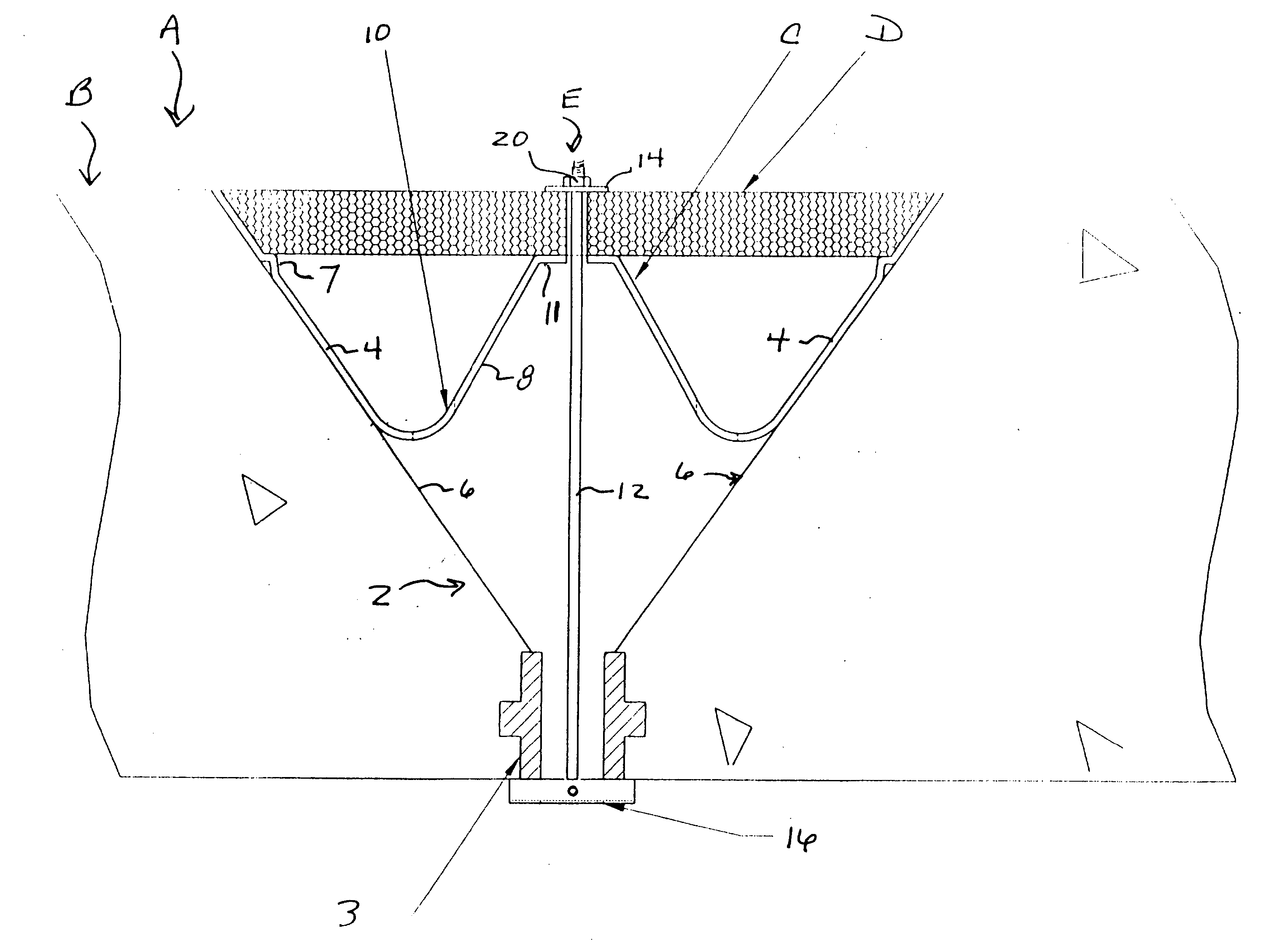
[0027] The preferred forms of the invention will now be described with reference to FIGS. 1-8. The appended claims are not limited to the preferred forms and no term used herein is to be given a meaning other than its ordinary meaning unless it is expressly stated that the term shall have a special meaning. The only term in this Specification having a special meaning is the term "insert." As used herein "insert" does not include within its meaning a porous plate, i.e., a porous plate is not an insert.

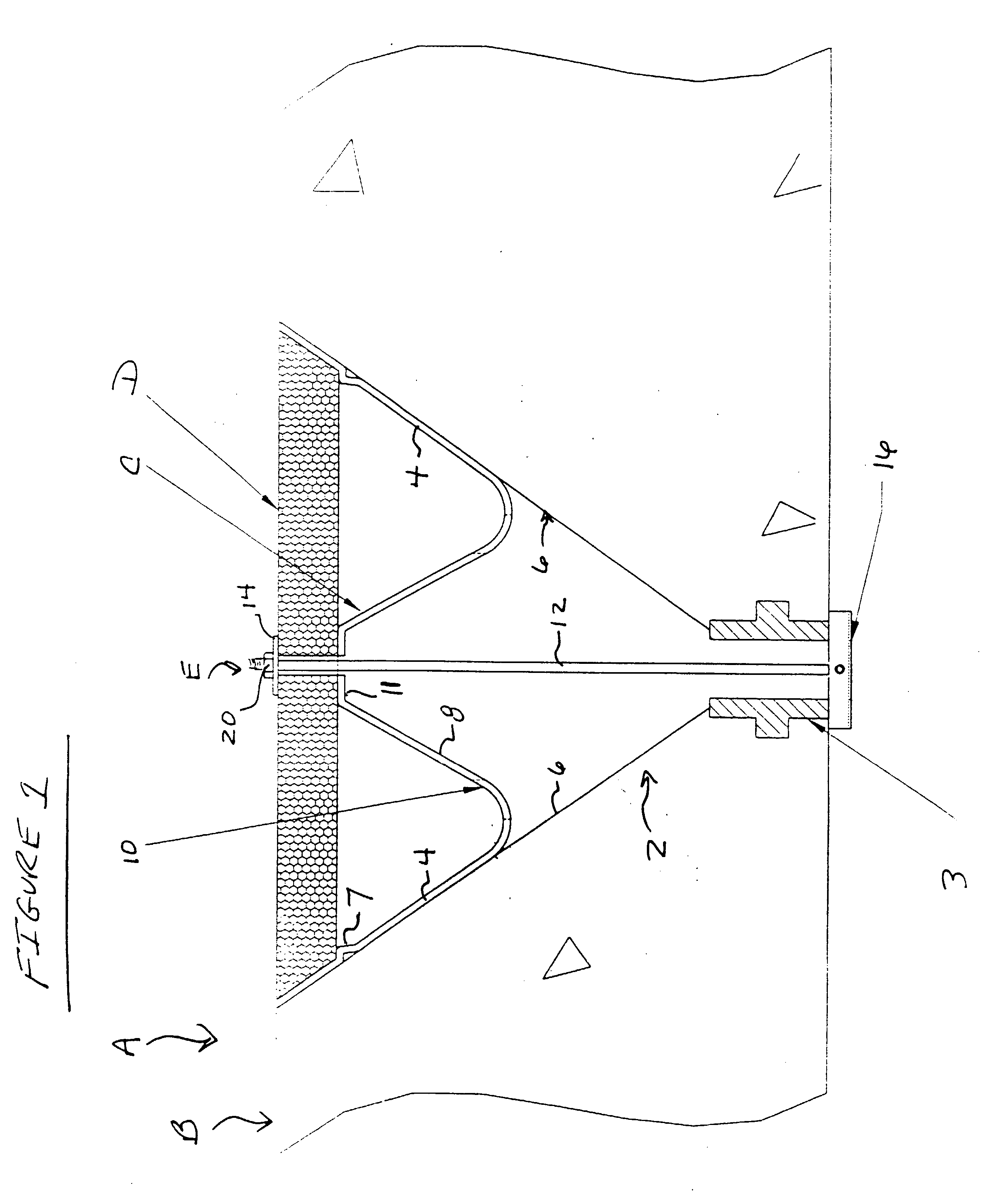
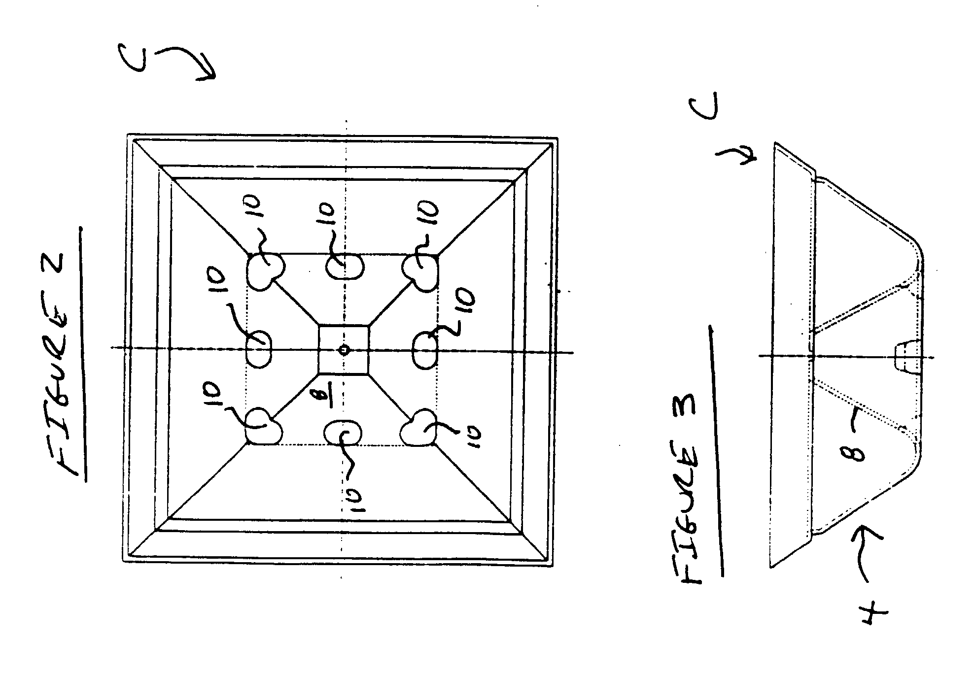
FIGS. 1 Through 3

[0028] Referring to FIG. 1, a portion of an underdrain system A is illustrated in one of many possible configurations. The underdrain system A includes a false-bottom underdrain structure B. The false bottom filter underdrain structure B is preferably formed of concrete and includes a plurality of hoppers 2 (only one of which is shown). The false bottom underdrain structure B can either be of the pre-cast or monolithic construction. Where the false bottom underdrain str...


PUM

PropertyMeasurementUnit
sizeaaaaaaaaaa
sizeaaaaaaaaaa
timeaaaaaaaaaa

Abstract

An underdrain system having a bottom formed of concrete. The concrete bottom includes a plurality of depressions formed therein. A porous plate is operably associated with at least one of the depressions. An anchor assembly is provided for anchoring the porous plate to the concrete bottom in an efficient and cost effective manner. Preferably, the anchor assembly permits the porous plate to be readily replaced. An optional insert may be used to enhance the distribution of the flow of fluid through the porous plate.

Description

[0001] The subject patent application is a continuation-in-part of U.S. patent application Ser. No. 09 / 948,798 filed on Sep. 10, 2001, the entire contents of which are incorporated herein by reference.[0002] The present invention is directed to significant improvements to underdrain systems generally and in particular false bottom (e.g., pre-cast and / or monolithic) underdrain systems that are used in filter systems for filtering water or wastewater.[0003] Various underdrain systems have been developed for filter systems that filter water and wastewater. One commonly used underdrain system is a monolithic false bottom underdrain system. This underdrain system typically includes a cast in place concrete structure that overlays the structural floor or true bottom of the filter housing or compartment. The concrete structure includes a plurality of cone shaped depressions formed herein. "Cone shaped" as used herein includes within its definition pyramidal shaped depressions. A thimble is...

Claims


Application Information

Patent Timeline
Patent Type & Authority Applications(United States)
IPC IPC(8): B01D24/24
CPCB01D24/24B01D24/4631
Inventor ROBERTS, R. LEEADDISON, MARK KEVIN
Owner RG DELAWARE
Learn More