Reduced density foam articles and process for making

a foam article and density reduction technology, applied in the field of reduced density foam articles, to achieve the effect of further reducing the density of the foam articl

Inactive Publication Date: 2004-02-19
3M INNOVATIVE PROPERTIES CO
View PDF38 Cites 6 Cited by
  • Summary
  • Abstract
  • Description
  • Claims
  • Application Information

AI Technical Summary

Benefits of technology

[0005] In one aspect of the present invention, an unfoamed barrier layer on a foam layer is employed to produce reduced density foam articles. It is believed that incorporating an unfoamed layer onto a major surface of a layer of foamable material acts as a barrier and dramatically changes the diffusional characteristics of a fugitive gas in the foamable material. This provides the ability to foam materials that may otherwise be difficult to foam.
[0082] The inventors found that increasing the thickness of the barrier layers caused more fugitive gas to remain in the foamable layer and expand thereby causing the density of a foam article to significantly decrease. Thicker barrier layers also provide mechanical support to the resulting foam article.

Problems solved by technology

Methods for producing reduced density thermoplastic foam articles often employ flammable hydrocarbon gases as a physical blowing agent or employ complicated and costly crosslinking technologies.

Method used


Image

  • Reduced density foam articles and process for making
  • Reduced density foam articles and process for making
  • Reduced density foam articles and process for making

Examples


example 3

[0110] The foam articles of this example were made with a foamable layer having a gas concentration of about 73.0 volume percent.

[0111] The foam articles of Example 3 were made and tested in the same manner as those in Comparative Example 1 except that 6 wt % RIC-50 was used as a blowing agent, and the screw RPM of extruder 24 and the line speed were different. Operating conditions and test results are shown in Table 3.

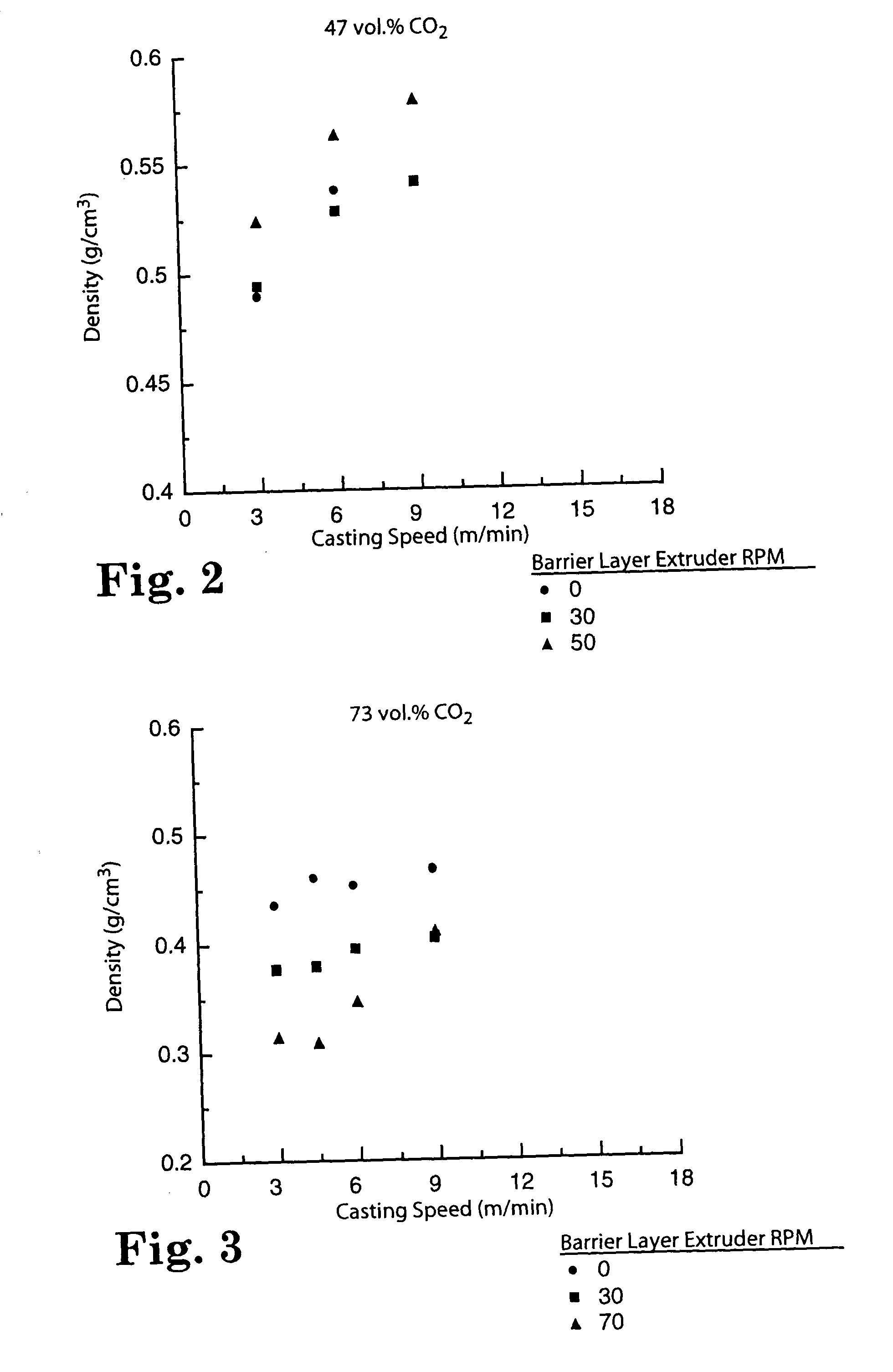
[0112] Surprisingly, the data in Table 3 show that, for these ABA foam articles made with a 73.0% vol. CO.sub.2 fugitive gas concentration in the B layer, at a given casting speed, density decreased as barrier layer thickness increased. The data in Table 3 are shown graphically in FIG. 3.

3 TABLE 3 A Layer Final Material FinalTotal B Layer Thick- Flow- Casting Thick-RIC-50 CO.sub.2 T.sub.m P.sub.m Gas ness rate Speed Density ness Example Wt % wt % .degree. C. MPa vol % Mat'l RPM .mu.m kg / hr m / min g / cm.sup.3 .mu.m 3A 6.0 none 173 14.9 73.0 None 0 0 13.9 3.0 0.43 830 3B ...

example 4

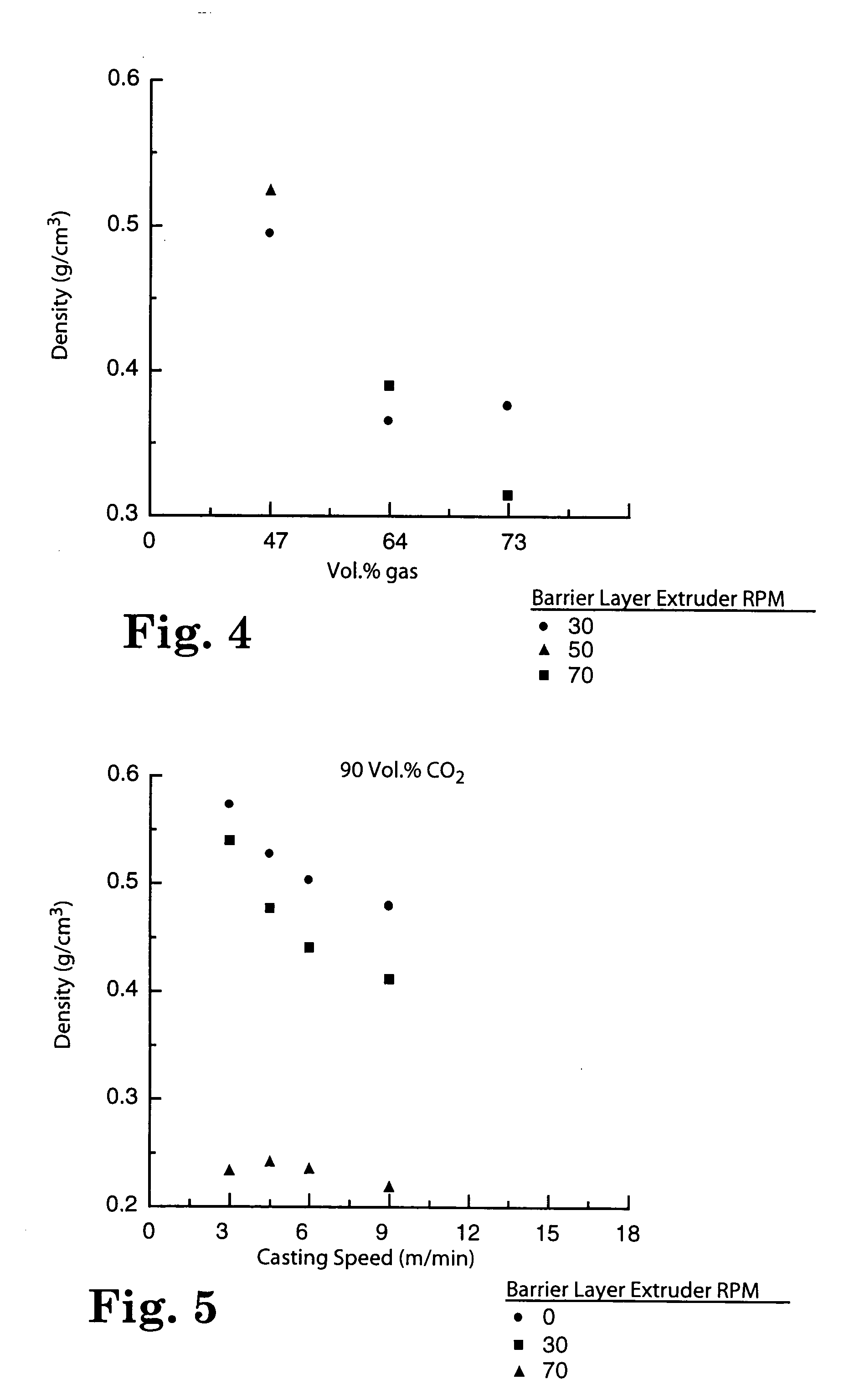
[0113] The foam articles of this example were made with a foamable layer having a gas concentration of about 90.0 volume percent.

[0114] The foam articles of Example 4 were made in the same manner as those in Comparative Example 1 except that a combination of 1.6 wt % carbon dioxide and 2 wt % RIC-50 were used as blowing agents, and the screw RPM of extruder 24 and the speed of casting drum 28 were different. The carbon dioxide gas (99.9%, Oxygen Services, St. Paul, Minn.) was introduced into extruder 14 at 0.23 kg / hr (0.5 lb / hr). Operating conditions and test results are shown in Table 4.

[0115] As the data in Table 4 show, for these ABA foam articles made with a 90.0% vol. CO.sub.2 fugitive gas concentration in the B layer, at a given casting speed, as barrier layer thickness increased foam density decreased by between 5 and 60%. For example, comparison of Examples 4A and 41 shows that adding a barrier layer having a final thickness of 84.3 .mu.m decreased foam density by almost 60%...

example 6

[0120] The foam articles of this example were made with barrier layers comprising a pressure sensitive adhesive KRATON available as HL2642X from H.B. Fuller, St. Paul, Minn., and a foamable layer having a gas volume concentrations of 90 vol. %.

[0121] The foam articles of Example 6 were made in the same manner as those in Comparative Example 5 except that a different blowing agent formulation was used. The blowing agent used was 2 weight % RIC-50 and 1.6 weight % CO.sub.2. Operating conditions and test results are shown in Table 6. Some of the data in Table 6 are shown in FIG. 6. Data for Examples 4B, 4C, and 4D, which were made using a similar gas volume percent are also shown in Table 6 for comparative purposes.

[0122] As the data in Table 6 shows, for these ABA foam articles made with a 90.0% vol. CO.sub.2 fugitive gas concentration in the B layer, at a given casting speed, foam density decreased as barrier layer thickness increased. For example, as shown by comparing 4D and 6F, in...


PUM

PropertyMeasurementUnit
boiling pointsaaaaaaaaaa

Abstract

The invention discloses reduced density foams and methods of making the foams by applying or creating a nonfoaming barrier layer on a foamable layer, which barrier layer inhibits the escape of fugitive gases during the foaming process.

Description

[0001] This application is a divisional of U.S. patent application Ser. No.: 09 / 714,408, filed Nov. 16, 2000, now allowed, the disclosure of which is herein incorporated by reference.[0002] This invention relates to reduced density foam articles and methods of making same.[0003] Methods for producing reduced density thermoplastic foam articles often employ flammable hydrocarbon gases as a physical blowing agent or employ complicated and costly crosslinking technologies. Nonvolatile gases such as carbon dioxide (CO.sub.2) and nitrogen are generally not preferred as a blowing agent for thermoplastics due to their low solubility in the polymer.SUMMARY OF INVENTION[0004] The present invention provides reduced density foam articles. These articles can be made with environmentally-friendly gases.[0005] In one aspect of the present invention, an unfoamed barrier layer on a foam layer is employed to produce reduced density foam articles. It is believed that incorporating an unfoamed layer o...

Claims


Application Information

Patent Timeline
Patent Type & Authority Applications(United States)
IPC IPC(8): C08J9/06B29C44/04B29C44/06B32B5/18B32B5/20B32B27/18B32B27/32B32B37/00C08J9/12C08J9/34C09J7/29
CPCB29C44/0407B29C44/065B32B5/20Y10T428/28C08J2201/03C09J7/0296C09J2400/243C08J9/34Y10T428/249953C09J7/29C09J2301/302
Inventor GEHLSEN, MARK DAVIDVALL, DAVID LORENALBRECHT, BONNIE WEISKOPF
Owner 3M INNOVATIVE PROPERTIES CO
Why Eureka
Try Eureka