
All-optical precision gunnery simulation (PGS) method and system

a technology of all-optical precision and gunnery simulation, applied in the field of all-optical precision gunnery simulation (pgs) method and system, can solve the problems of limited simulation range arising, limited exercise participation arising from the limited rf link channel capacity

Inactive Publication Date: 2004-02-19
CUBIC DEFENSE APPL
View PDF23 Cites 29 Cited by
  • Summary
  • Abstract
  • Description
  • Claims
  • Application Information

AI Technical Summary

Benefits of technology

[0011] It is a purpose of this invention to provide a PGS system that can simulate engagement at longer ranges, up to 4 km and more with eye-safe optical signal intensities. It is an advantage of this invention that it provides a PGS system that can operate in battlefield smoke and haze at eye-safe signal levels.
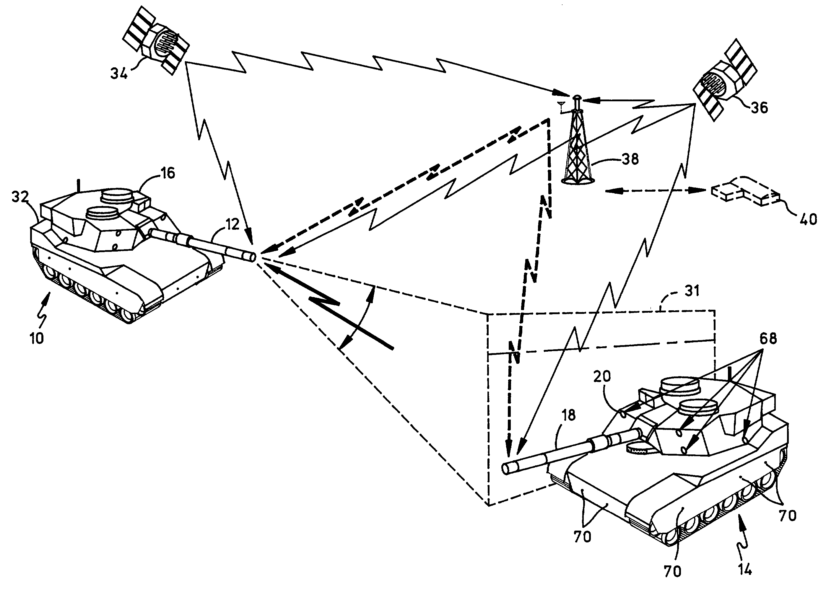
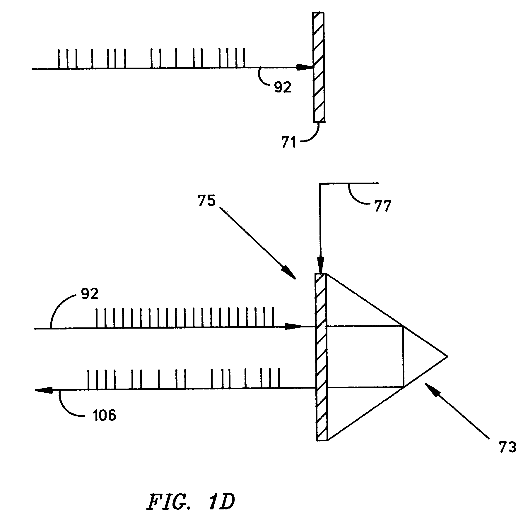
[0014] The PGS system of this invention permits all trajectory simulation and hit-miss assessment to be performed at the target, thereby advantageously permitting the shooter to "fire and forget" without holding station to monitor the target position. The simulation results may be returned to the shooter by passively modulating the retroreflection of an optical return window signal from the shooter. Alternatively, the PGS system of this invention permits the target to determine shooter position precisely from incoming optical pixel signal data for use in transmitting an active narrow-beam optical signal from the target back to the shooter if desired.

Problems solved by technology

Other disadvantages include the limited simulation range arising from the laser power limits imposed to comply with eye-safety requirements and the limited exercise participation arising from the limited RF link channel capacity.

Method used


Image

  • All-optical precision gunnery simulation (PGS) method and system
  • All-optical precision gunnery simulation (PGS) method and system
  • All-optical precision gunnery simulation (PGS) method and system

Examples


Embodiment Construction

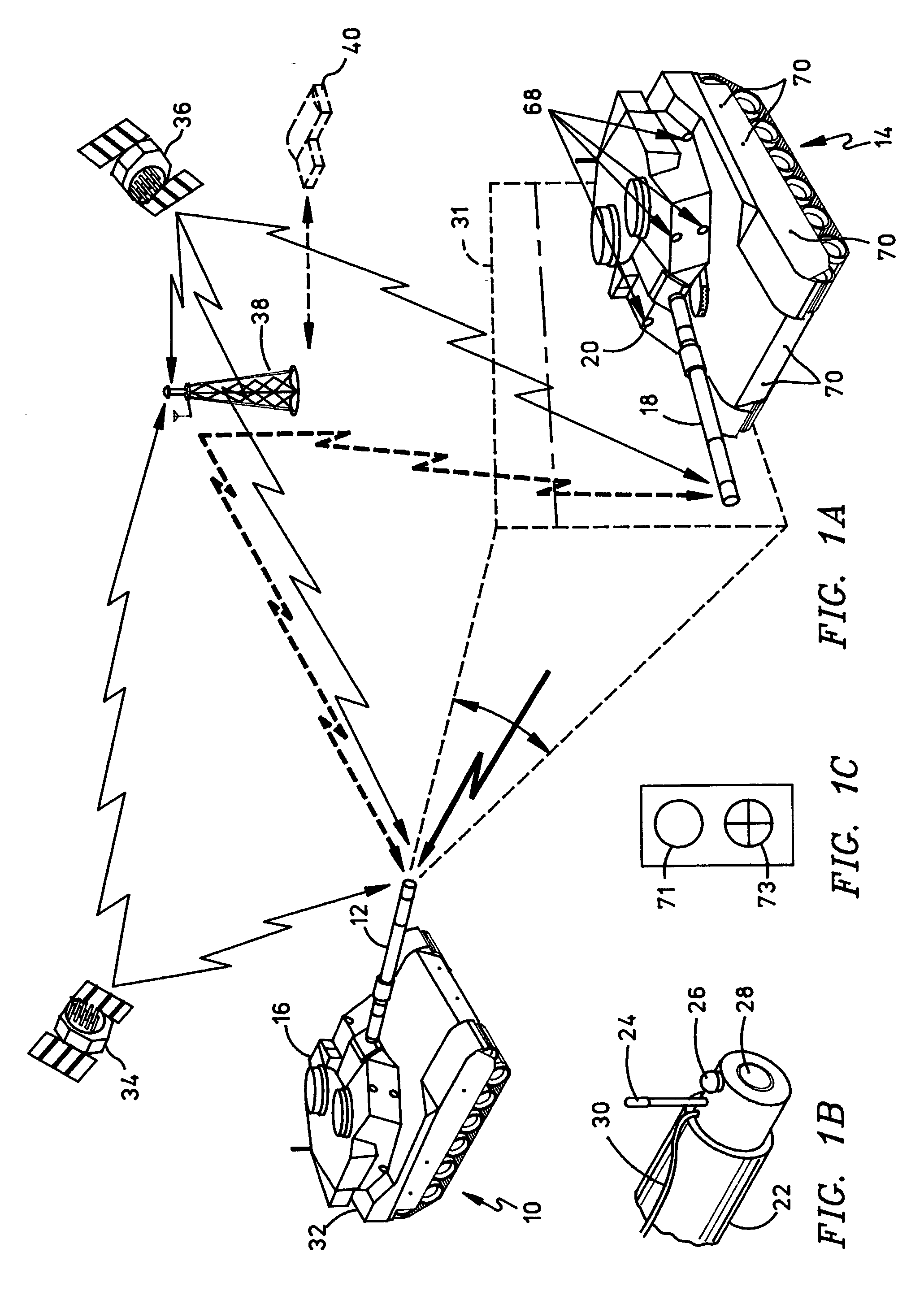
[0032] FIG. 1A illustrates the functional architecture of a preferred embodiment of the all-optical precision gunnery simulator (PGS) system of this invention. A first friendly tank or shooter 10 is shown engaging and firing its gun 12 upon a second enemy tank or target 14. Shooter 10 is at a first location and the target 14 is at a second location that may typically be several hundred meters from the first location. It should be understood that one or both of tanks 10 and 14 may be stationary or moving at speeds of sixty kilometers per hour or more. Gun 12 of shooter 10 is mounted on a stabilized turret 16 in any useful conventional fashion. Similarly, the gun 18 of enemy tank 14 is similarly mounted on a stabilized turret 20. By way of example, tanks 10 and 14 may be M1A1 main battle tanks with 120 millimeter guns having a normal firing range of 3,500 meters (with SABOT munition) and 2,500 meters (with HEAT munition).

[0033] As shown in FIG. 1B, each of tanks 10 and 14 has mounted ...


PUM


Abstract

An all-optical precision gunnery simulation (PGS) system that may be adapted to simulate many tactical gunnery scenarios. The eye-safe system of this invention uses a 1550 nanometer optical infrared (IR) signal to permit increased range and field-of-view (FOV) and reduced scintillation over that of the 904 nanometer IR signals known in the art. Temporal and spatial diversity permit error-free operation over long ranges through dust and scintillation. The system performs all trajectory simulation and hit-miss assessment at the target, thereby permitting the shooter to "fire and forget" without holding station to monitor the target position. The simulation results may be reported to the shooter by passively modulating the retroreflection of an optical return window signal from the shooter. Alternatively, the target may compute shooter position from incoming optical pixel signal data for use in reporting by means of an active narrow-beam optical signal from the target back to the shooter.

Description

CROSS-REFERENCES TO RELATED U.S. PATENT[0001] This application is related by common inventorship and subject matter to the commonly-assigned U.S. Pat. No. 6,386,879 B1, filed on Mar. 24, 2000 as patent application Ser. No. 09 / 534,773 by Varshneya et al. under the title "PRECISION GUNNERY SIMULATOR SYSTEM," which is entirely incorporated herein by reference.[0002] 1. Field of the Invention[0003] This invention relates generally to military training systems and more particularly to a system and method for simulating heavy weapon fire in military training exercises.[0004] 2. Description of the Related Art[0005] Explosive-powered artillery has long been classified according to the path or trajectory of its projectile, which is related to the size of the propulsive charge employed. A mortar lobs its shell in a high parabolic path using a relatively light propulsive charge. The shell fired from a cannon or gun, such as a tank gun, is intended for rapid line-of-sight targeting and has an e...

Claims


Application Information

Patent Timeline
IPC IPC(8): F41G3/26
CPCF41G3/265F41G3/2688F41G3/2666F41G3/2655
Inventor VARSHNEYA, DEEPAK
Owner CUBIC DEFENSE APPL
Learn More