
Heat recovery system

Inactive Publication Date: 2004-03-11
NOAH NORMAN CHESTER
View PDF12 Cites 16 Cited by
  • Summary
  • Abstract
  • Description
  • Claims
  • Application Information

AI Technical Summary

Benefits of technology

[0007] Another objective of the present invention is to provide a system for improved heating and cooling capabilities that can be retrofitted to existing heating and cooling systems.
[0008] Yet another objective of the present invention is to provide an improved heating and cooling system that will advantageously utilize the accumulated heat energy normally found in the attics of homes and buildings particularly during the hot summer months and especially in the space between roof rafters, the roof inside surface and a barrier material attached to the free inside edges of the roof rafters.
[0009] A further objective of the present invention is to provide a system of the type described which is less expensive than the utilization of solar panels to convert heat energy into other usable energy forms.
[0010] Yet a further objective of the present invention is to provide an improvement in a heating and cooling system of the type described which can be used to bring the temperature of air in the attic of a residence or building near the temperature of the outside air thereby making the attic a more user friendly location throughout the year.
[0016] The present invention is easily applied to existing heat pump installations where it can supplement or replace the existing heat pump system when conditions are appropriate, or it can be bypassed to let the conventional system operate in its usual way.

Problems solved by technology

Solar panels are very expensive, and the placement of numerous panels on the roof of a structure detracts from the structure's appearance to a considerable degree.
Other attempts to utilize the heat normally building in the attic of a home involve costly additions to the home or significant modification to existing structure, in order to attempt to improve the heating and cooling capacity.
No significant improvements have been yet found that will utilize the high temperatures normally experienced in the attics of homes during hot weather or other energy saving activities that can be associated therewith.

Method used


Image

  • Heat recovery system
  • Heat recovery system
  • Heat recovery system

Examples


Embodiment Construction

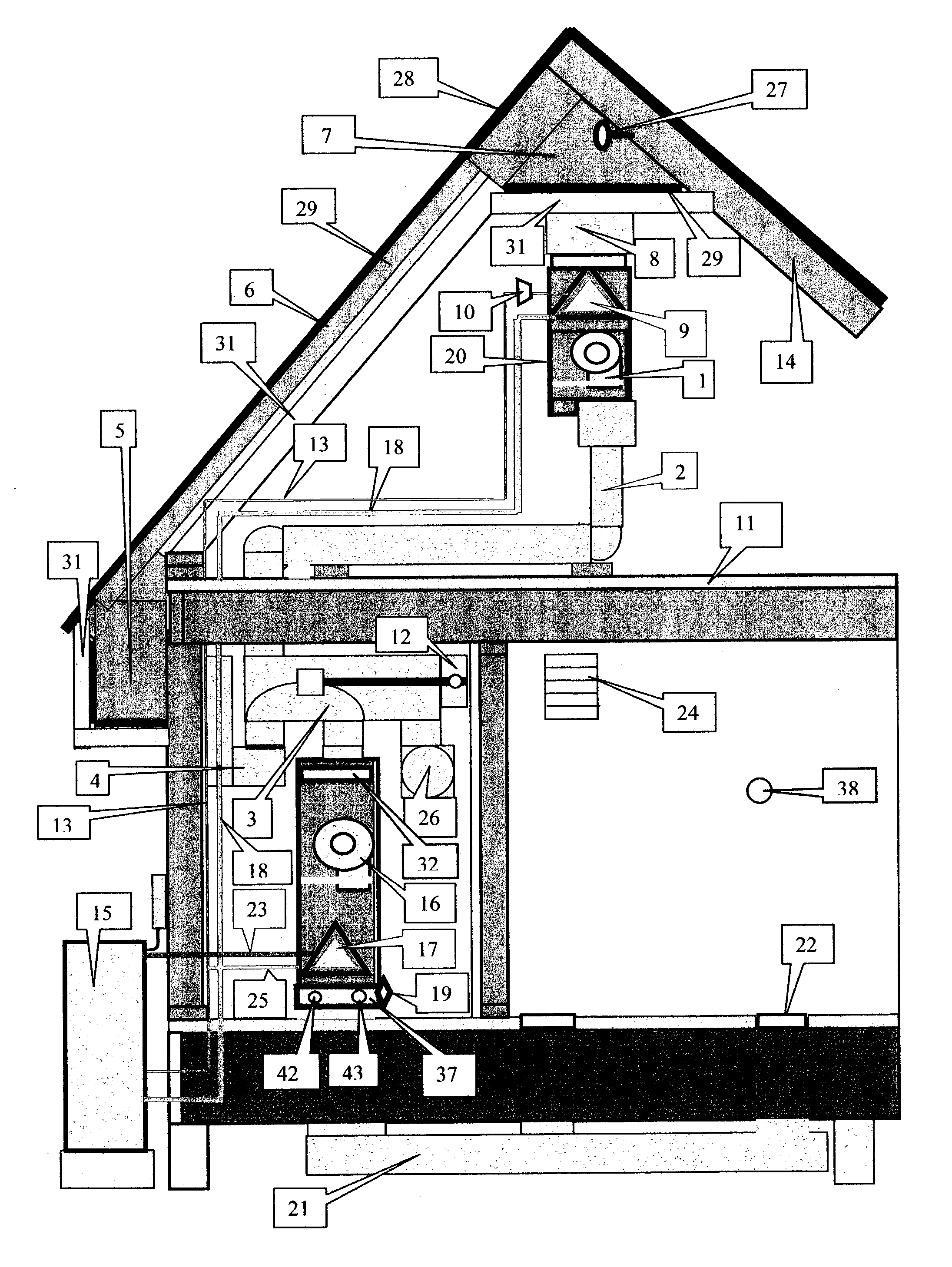
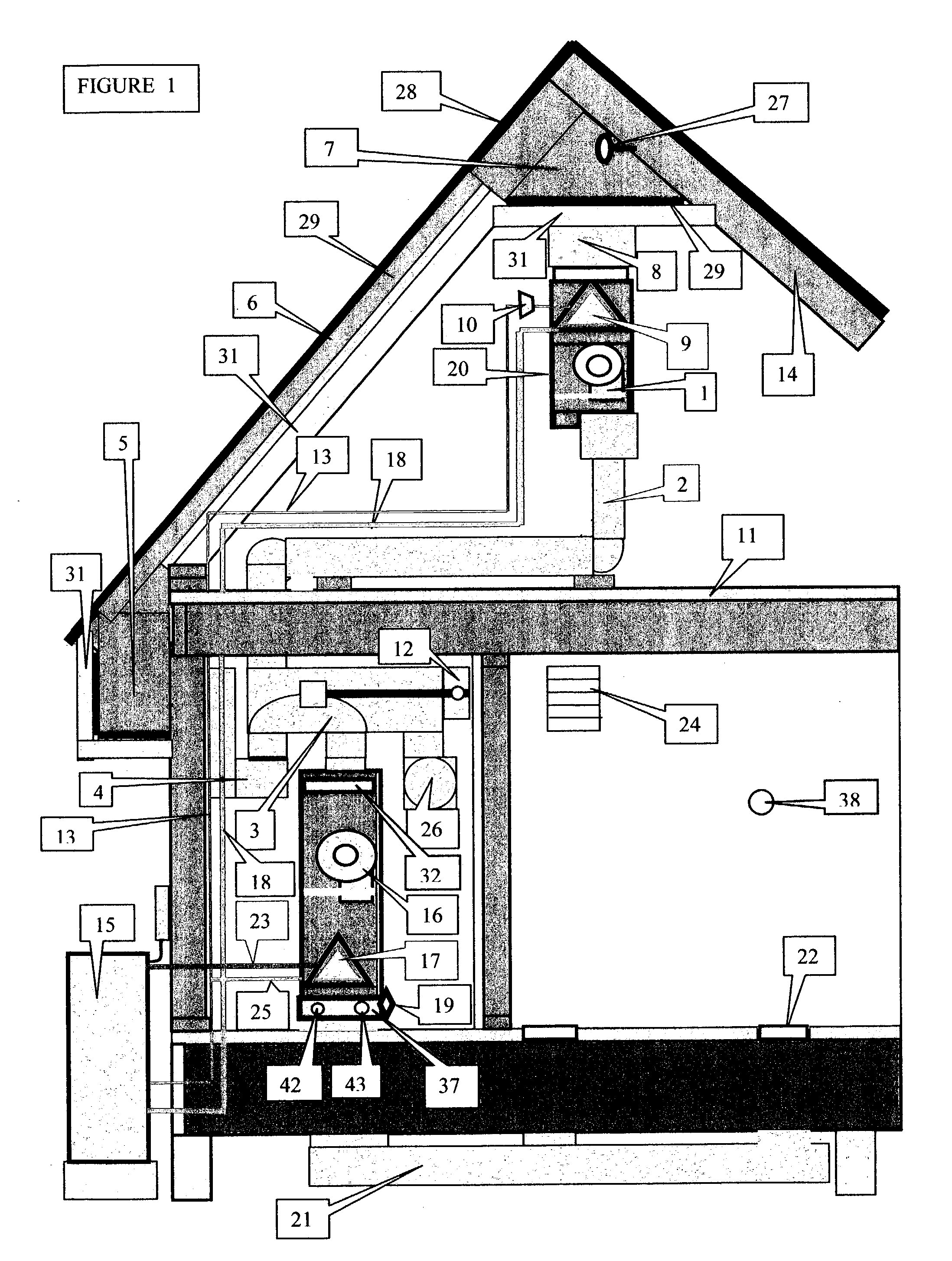
[0035] FIG. 1 thermostat 38 calling for heat and attic censer 26 senses that there is adequate heat in space 7 to heat the house or building starts blower 16. for 3 minutes then blower 16 stays on by censer 19 and blows air through A coil 17 through water to air heat exchanger 37 through supply ducting system 21 through supply registers 22 through return air register 24 through return air ducting system 26 through reversing valve 3 through attic ducking 2 through attic air handler 20 through air space above the upper attic floor behind insulation 31 down through small air spaces between the rafters 6 picking up heat from roof 28 through boxed end eve through duct 4 through reversing valve 3 through filter 32 to blower 16 to be recycled.

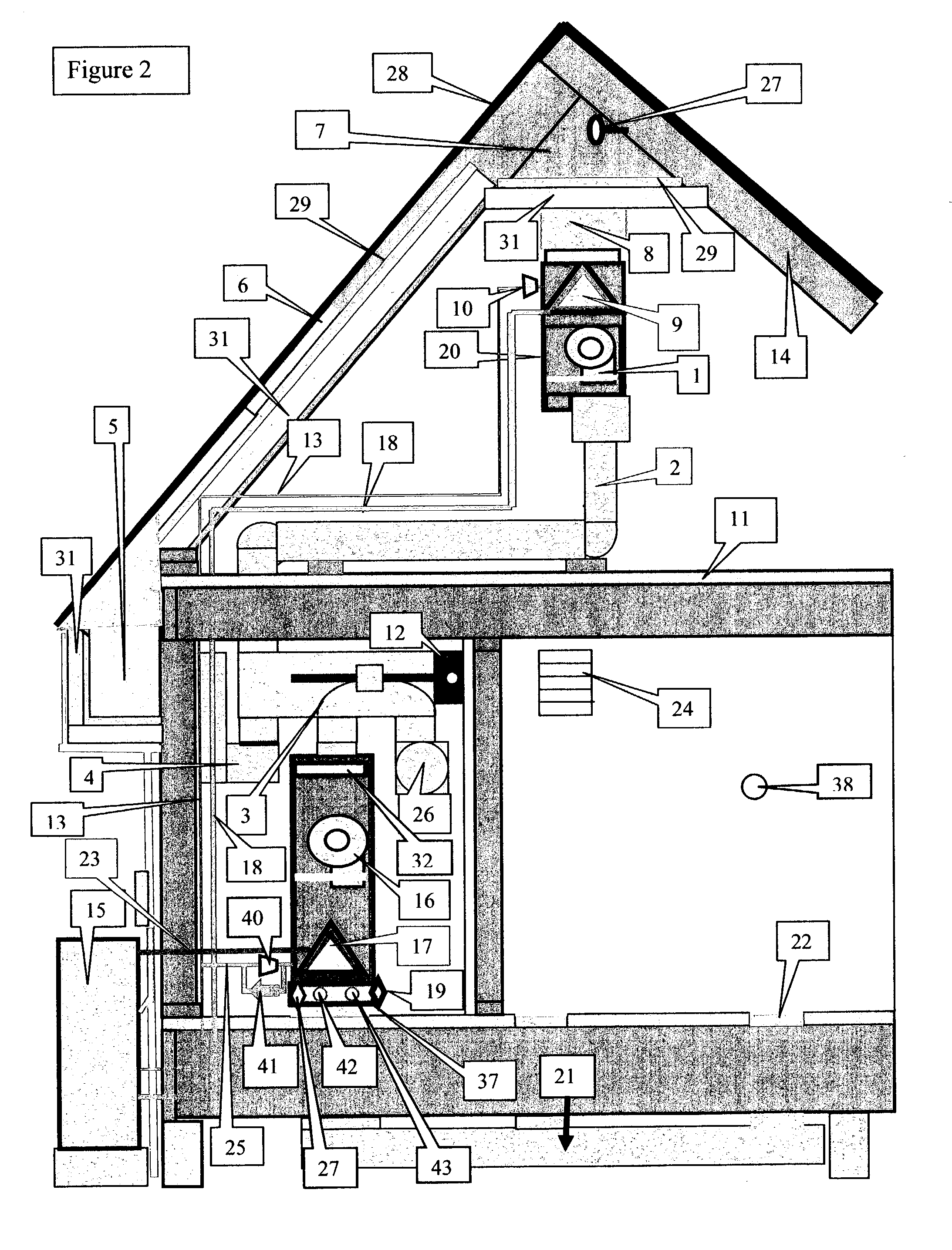
[0036] FIG. 2 heating cycle Thermostat 38 calling for heat turns on blower 1 and blower 16. Ref. FIG. 4 thermostat turns on compressor 1, hot water isolation switch 40, reversing valve 20 and fan 35. Blower 1 blows air through attic ducting 2 through ...


PUM


Abstract

This is a heating and cooling system, and method that utilizes the roof of a home or building as a solar collector. A heat barrier material is secured to the inside free edges of the roof rafters to reflect radiant heat into air flow passage ways formed between the rafters, the attic side of the roof and the heat barrier materials. A loft or upper attic floor is built in the upper portion of the attic and is also covered with the heat barrier material. The attic is divided into separate areas that are connected by a ducting system that includes a filter, an evaporator and a blower. The blower produces airflow through the filter and over the evaporator coil and into a separated portion of the attic. Airflow moves through selected formed channels between rafters, barrier material and inside roof to the blower for re-circulation. This closed loop system is usable with conventional air-to-air heat pump systems, with portions of such systems or with other well-known devices such as heat exchangers and heat engines.

Description

[0001] 1. Field of the Invention.[0002] The present invention relates to improvements in heating and cooling systems and more particularly to a system using up to the entire roof of a home or building as a solar collector by isolating a portion of the attic and utilizing a blower, evaporator and filter to draw heated air over the evaporator coil, exhausting the heat in various ways and returning it to be recycled.[0003] 2. Description of the Prior Art.[0004] Numerous attempts have been made to utilize the heat that builds in the attic of a home or building in a meaningful way to improve heating and cooling efficiency or produce power for other uses. A common approach has been to utilize solar panels for the generation of heat and energy from the sun, but usually these panels must be placed on the roof of the structure in order to operate in the most efficient manner possible. Solar panels are very expensive, and the placement of numerous panels on the roof of a structure detracts fr...

Claims


Application Information

Patent Timeline
IPC IPC(8): F24F5/00F24J2/04F25B13/00F25B27/00F25B41/00
CPCF24F5/0046Y02E10/44F25B13/00F25B27/005F25B41/00F25B2313/0232F25B2313/02334F25B2313/0252F25B2313/0253F25B2313/02743F25B2313/0315F25B2400/0401F25B2700/2115Y02B10/20Y02B10/24F24J2/045F24S20/67Y02E10/40Y02A30/60
Inventor NOAH, NORMAN CHESTER
Owner NOAH NORMAN CHESTER
Features
  • Generate Ideas
  • Intellectual Property
  • Life Sciences
  • Materials
  • Tech Scout
  • Unparalleled Data Quality
  • Higher Quality Content
  • 60% Fewer Hallucinations
Learn More