Processing apparatus and cleaning method

Inactive Publication Date: 2004-04-08
TOKYO ELECTRON LTD
View PDF6 Cites 22 Cited by
  • Summary
  • Abstract
  • Description
  • Claims
  • Application Information

AI Technical Summary

Benefits of technology

0008] The present invention has been made in consideration of the above. It is accordingly an object of the present i

Problems solved by technology

Thus formed films cause particles to be generated, thereby lowering the yield of the products.
However, plasma is generated inside the chamber, so that the chamber member is likely to be deteriorated.
Using this remote plasma cleaning method, the chamber member is unlikely to be deteriorated.
A problem in the remote plasma cleaning method is that it requires a relatively long period of time for

Method used


Image

  • Processing apparatus and cleaning method
  • Processing apparatus and cleaning method
  • Processing apparatus and cleaning method

Examples


Example

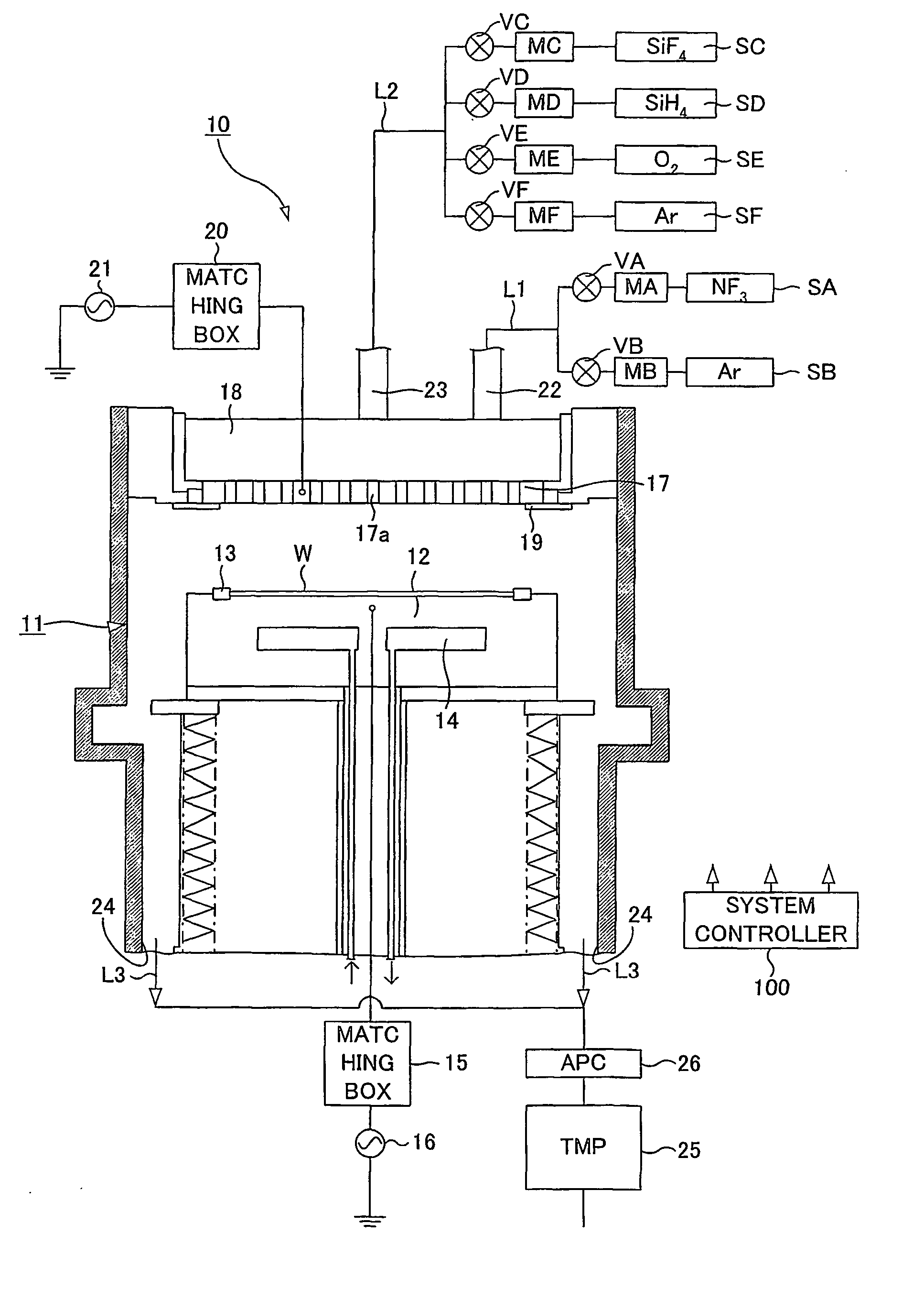
[0056] In this Example 1, during a film formation, a SiOF film is formed to have a thickness of 5 .mu.m on the wafer W, within the distance 50 mm between the electrodes. In addition, during a cleaning process, the system controller 100 supplies the chamber 11 with NF.sub.3 / Ar=500 / 500 (sccm / sccm) at a pressure of 13 Pa, and applies an RF power of 1500W to the upper electrode (the electrode plate 17).

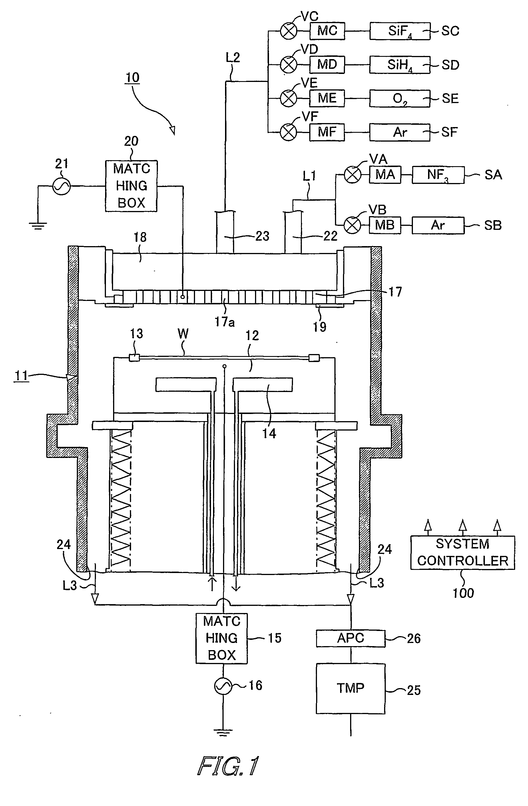
[0057] FIG. 2 shows the relationship between the cleaning time and the applied RF power, in the case where the cleaning is performed with applying the RF power to the upper and lower electrodes using the processing apparatus of the first embodiment. As seen from FIG. 2, it is clear that the processing apparatus which applies the RF power to the upper and lower electrodes can achieve the cleaning at a shorter period of time than the case where the RF power is applied only to the upper electrode. In the case where RF powers of 300W and 500W are applied to the lower electrode, the cleaning t...

Example

EXAMPLE 2

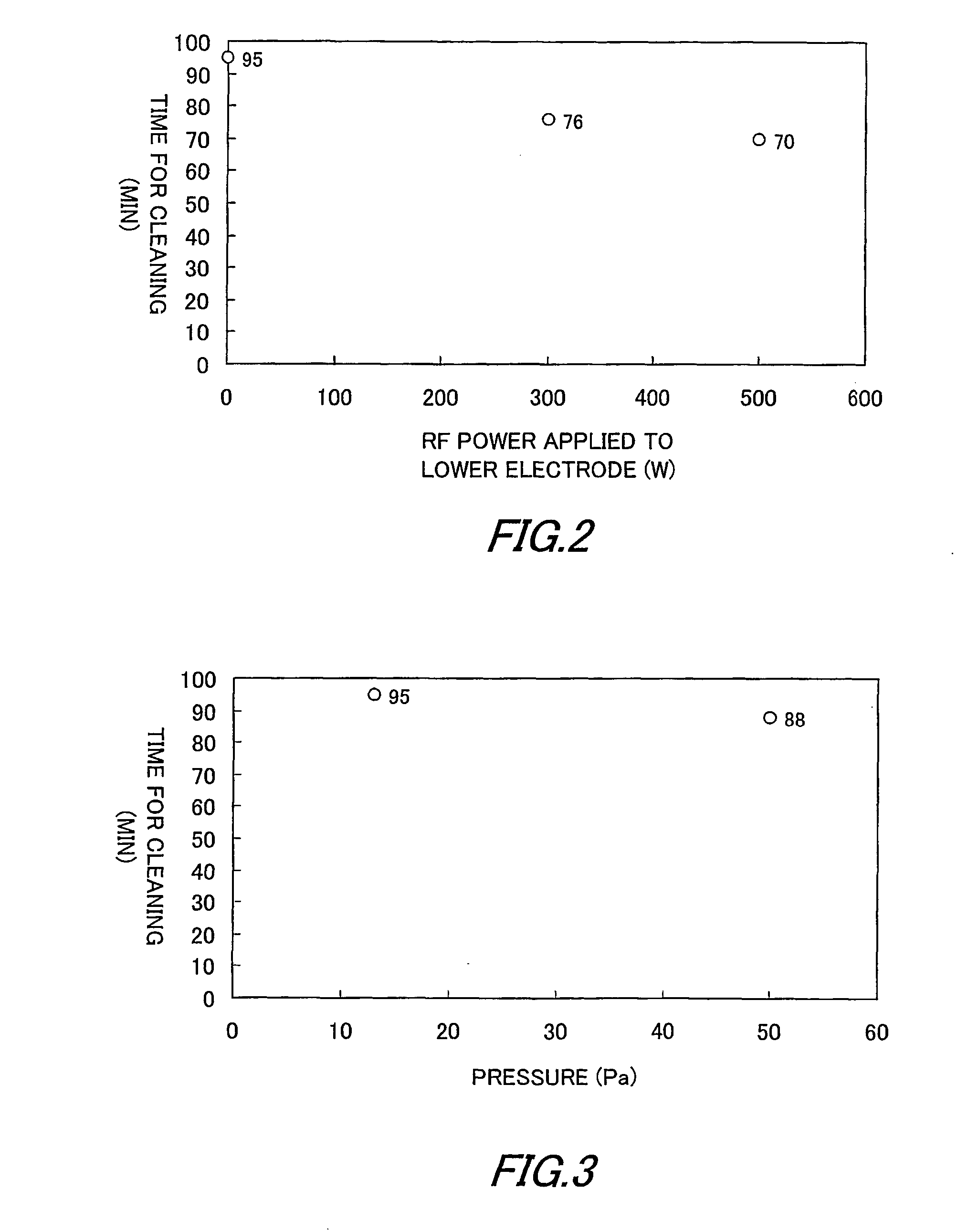
[0071] FIG. 6 shows the relationship between the time for cleaning and the pressure inside the chamber 11, and shows some results of the cleaning done after the film formation, using the processing apparatus according to the second embodiment of the present invention. In Example 2, during the process for forming the film, a SiOF film is formed to have a thickness of 5 .mu.m on the wafer W, with the distance of 50 mm between the electrodes.

[0072] FIG. 6 shows the results of the cleaning with a variety of pressure levels. As seen from FIG. 6, as compared to the case where the pressure inside the chamber 11 is in a high vacuum state of approximately 0 Pa, a high cleaning rate can be obtained if the pressure is within a range between 100 Pa and 400 Pa. Note also that, in the case where the pressure inside the chamber 11 is approximately 200 Pa, the most highest cleaning rate can be obtained. According to the second embodiment wherein the cleaning is performed at a pressure in a...

Example

EXAMPLE 3

[0073] In the above-described second embodiment, an RF power may be applied to the upper electrode. This realizes that the cleaning gas (mainly containing fluorine radical) activated outside the chamber 11 can further be activated inside the chamber 11. According to this structure, a high cleaning rate can be obtained.

[0074] FIG. 7 shows the relationship between the time for cleaning and the RF power applied onto the upper electrode, in the case where the cleaning is performed after the SiOF film is formed on the wafer W in a thickness of 5 .mu.m. During the cleaning, an RF power of 500W is applied to the upper electrode, and the pressure inside the chamber 11 is 200 Pa.

[0075] As obvious from FIG. 7, if the RF power is applied to the upper electrode and a remote plasma gas is used for cleaning the chamber 11, the cleaning is achieved at a cleaning time which is shorter than one fifth of the cleaning time in the case where the RF power is not applied thereto. Accordingly, wi...


PUM

PropertyMeasurementUnit
Fractionaaaaaaaaaa
Fractionaaaaaaaaaa
Pressureaaaaaaaaaa

Abstract

Provided is a parallel-plate-type processing apparatus (10), which performs plasma CVD and includes a chamber (11) to be cleaned. To perform cleaning of the chamber (11), plasma of a gas including fluorine is generated outside the chamber (11), and supplied into the chamber (11). During the cleaning, an RF power is applied to electrode plates (12, 17) inside the chamber (11).

Description

[0001] The present invention relates to a processing apparatus and a cleaning method in which an efficient cleaning is possible.[0002] Various CVD (Chemical Vapor Deposition) apparatuses are used for manufacturing electronic devices, such as semiconductor devices, LCD (Liquid Crystal Display) devices, etc. Plasma CVD apparatuses are widely used for forming high quality films.[0003] The plasma CVD apparatus forms a film on a semiconductor wafer contained inside a decompressed chamber, using a CVD method. The CVD method employs a gas phase reaction. Thus, films are formed only on the surface of the wafers, but on the surface (internal wall, etc.) of a chamber member. Thus formed films cause particles to be generated, thereby lowering the yield of the products. In such circumstances, it is necessary to regularly clean the inside of the chamber, to remove the films formed on the chamber member.[0004] A well-known method for cleaning the inside of the chamber is an in-situ plasma cleanin...

Claims


Application Information

Patent Timeline
IPC IPC(8): B08B7/00C23C16/44H01J37/32H01L21/205H01L21/302H01L21/3065
CPCB08B7/0035C23C16/4405H01J37/32862H01J37/3244C23C16/4411H01L21/205
Inventor OKA, SHINSUKEYOKOYAMA, OSAMUNAKASE, RISAISHIZUKA, SHUUICHI
Owner TOKYO ELECTRON LTD
Why Eureka
Try Eureka