System, method and apparatus for sharing and optimizing packet services nodes

a packet service and packet technology, applied in the field of telecommunications, can solve the problems of exponential demand for internet protocol (ip) networks and their services, service providers are struggling to find means to reduce operational and capital expenses, and the problem of even further problems

Inactive Publication Date: 2004-04-08
NASSAR AYMAN ESAM
View PDF15 Cites 142 Cited by
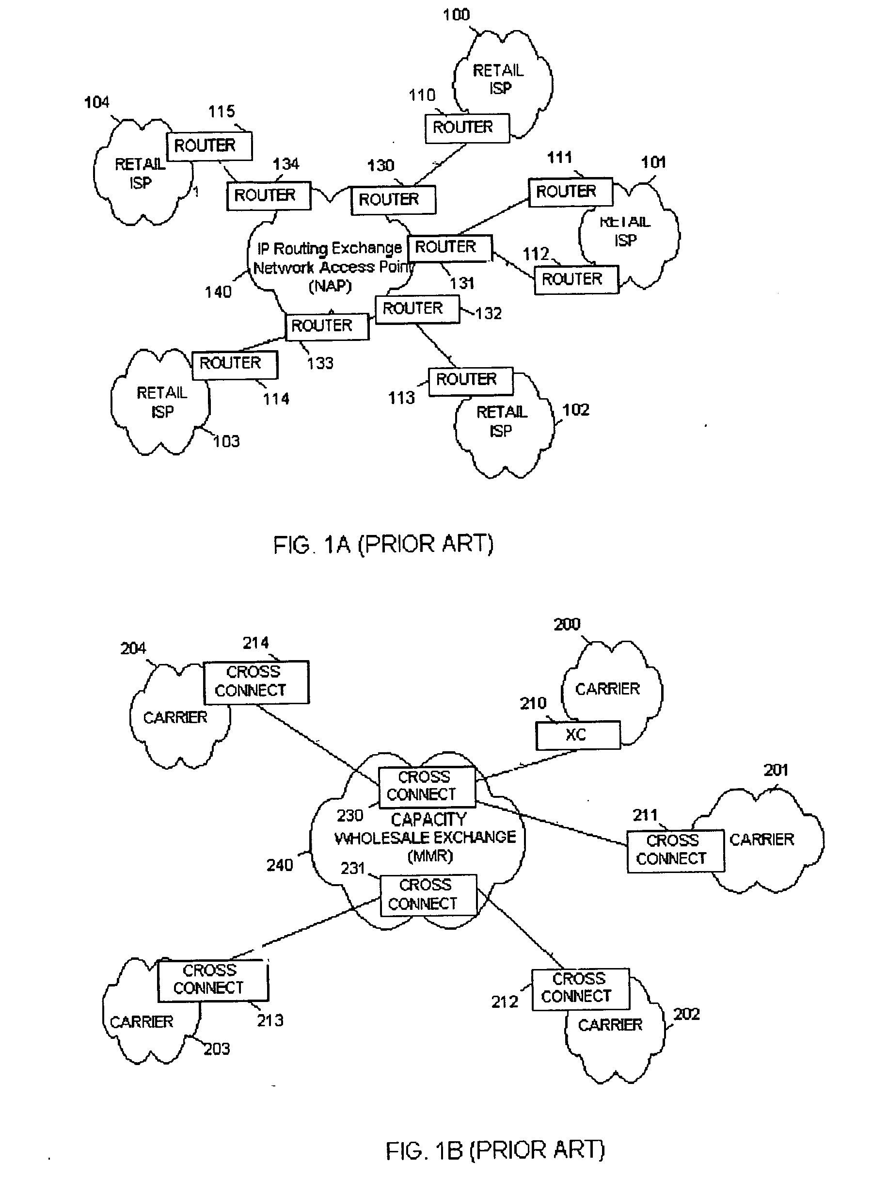
  • Summary
  • Abstract
  • Description
  • Claims
  • Application Information

AI Technical Summary

Problems solved by technology

Service providers have been struggling to find means to reduce operational and capital expenses, and improve revenue streams.
These challenges have been magnified by the explosive growth in Internet traffic resulting in an exponential demand for Internet Protocol (IP) networks and its services.
Additionally the fact that access services and backbone transit have emerged to become low-margin commodity services has compounded the problem even further.
While VRF offers the ability to achieve VPN services, it lacks the ability to provide a VPN user (site) full access to the configuration of the VPN resources, such as hardware and software resources.
Therefore, a VPN user of a virtual routing table also lacks security and privacy.
However, these methods are

Method used


Image

  • System, method and apparatus for sharing and optimizing packet services nodes
  • System, method and apparatus for sharing and optimizing packet services nodes
  • System, method and apparatus for sharing and optimizing packet services nodes

Examples


second embodiment

[0079] In the invention, firewall 705 could be implemented in software and be running as an application on RTOS 706.

third embodiment

[0080] In the invention and referring to FIG. 6, line boards 732a-c and traffic processor boards 731a-c could be realized on a single hardware board.

[0081] Furthermore, in a fourth implementation embodiment of the invention line boards 732a-c, traffic boards 731a-731c, master switching element 730, firewall 705 and master controller hardware board 703 could be implemented into one single hardware subsystem.

[0082] In a fifth implementation embodiment the master controller board 703 could be a separate hardware subsystem, the master switching element 730 could be another separate hardware subsystem, and the hardware elements of LCNs 740 and 760 be third and fourth and more hardware subsystem.

sixth embodiment

[0083] In the invention, the master switching element 730 and the LCN, such as 740 and 760 could implemented on the same hardware board. Many other possible embodiments can exist and the invention does not limit the realization into any particular implementation.

[0084] As will be noticed to those skilled in the art, the implementation embodiments could vary. Accordingly, the scope of the patented subject should not be limited to any of the specific exemplary implementations discussed.

[0085] The preferred embodiment is illustrated in FIG. 5A, in which components 703 and 705 of FIG. 6 are integrated into a single hardware subsystem 729a and a backup subsystem 729b. Switching element 730 is a separate hardware subsystem and UIS 512 is realized using two master switching elements, a primary switching element 730a and a backup switching element 730b. A number of traffic processor boards 731 (731a-731i) for additional loads are realized as in FIG. 5A. Line board 732 is also a separate mod...


PUM


Abstract

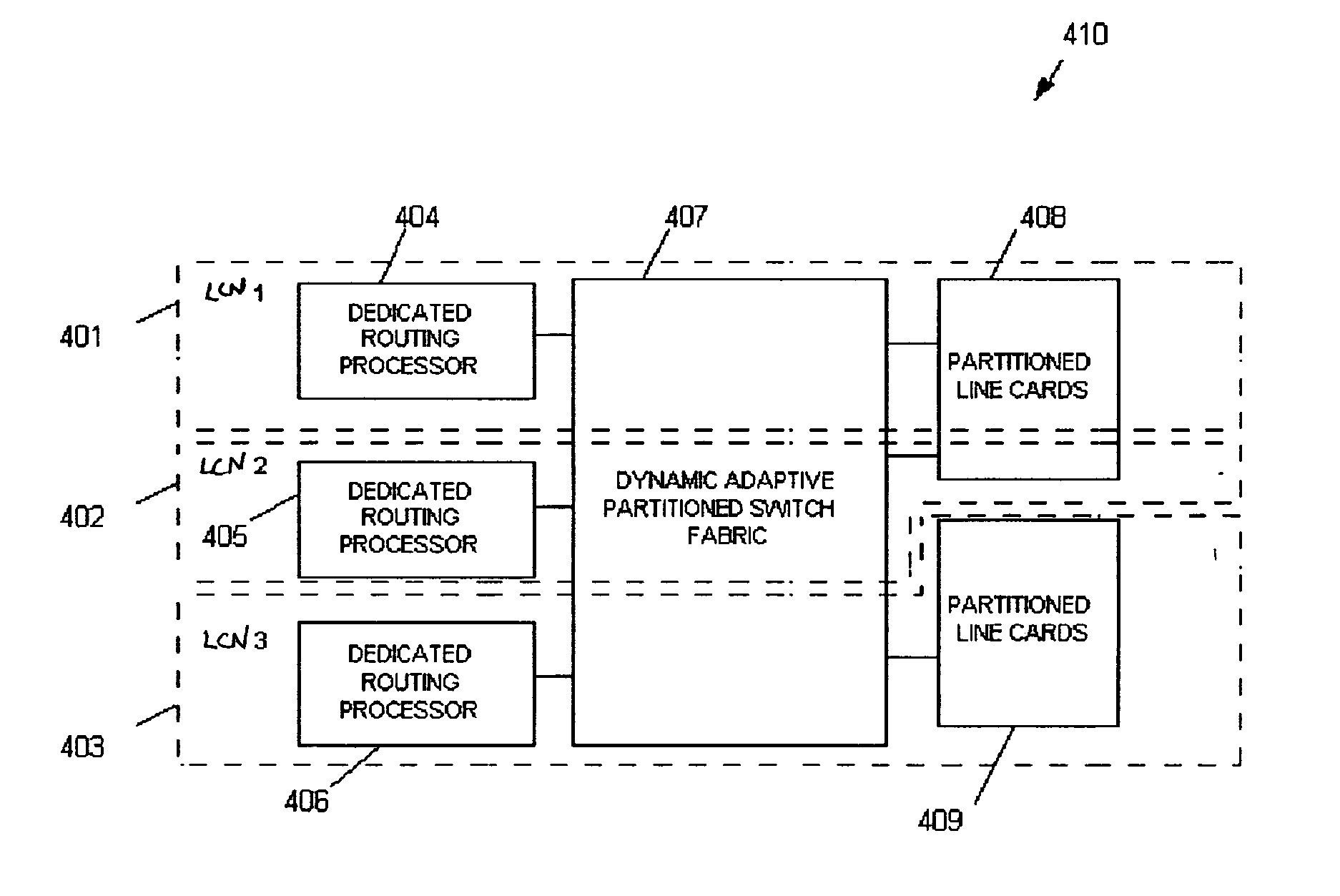
A dedicated, optimized, secure and private apparatus, system and method is provided for service providers to dynamically share the resources of a single packet services node within a telecommunications network. The apparatus, method and system uses real-time dynamic software partitioning, with low-level dynamic hardware reconfiguration and adaptation, to enable real-time network, software and hardware resource allocation. The packet services node is configured as a unified and integrated switch (UIS) that can be segmented into a number of logical communication nodes (LCN). Each LCN operates as a secure, independent, private and dynamically configured packet services node. A master controller is responsible for the allocation of resources to LCNs based on resource availability and/or a predefined resource allocation configuration between the operator of the UIS and the user of the LCN.

Description

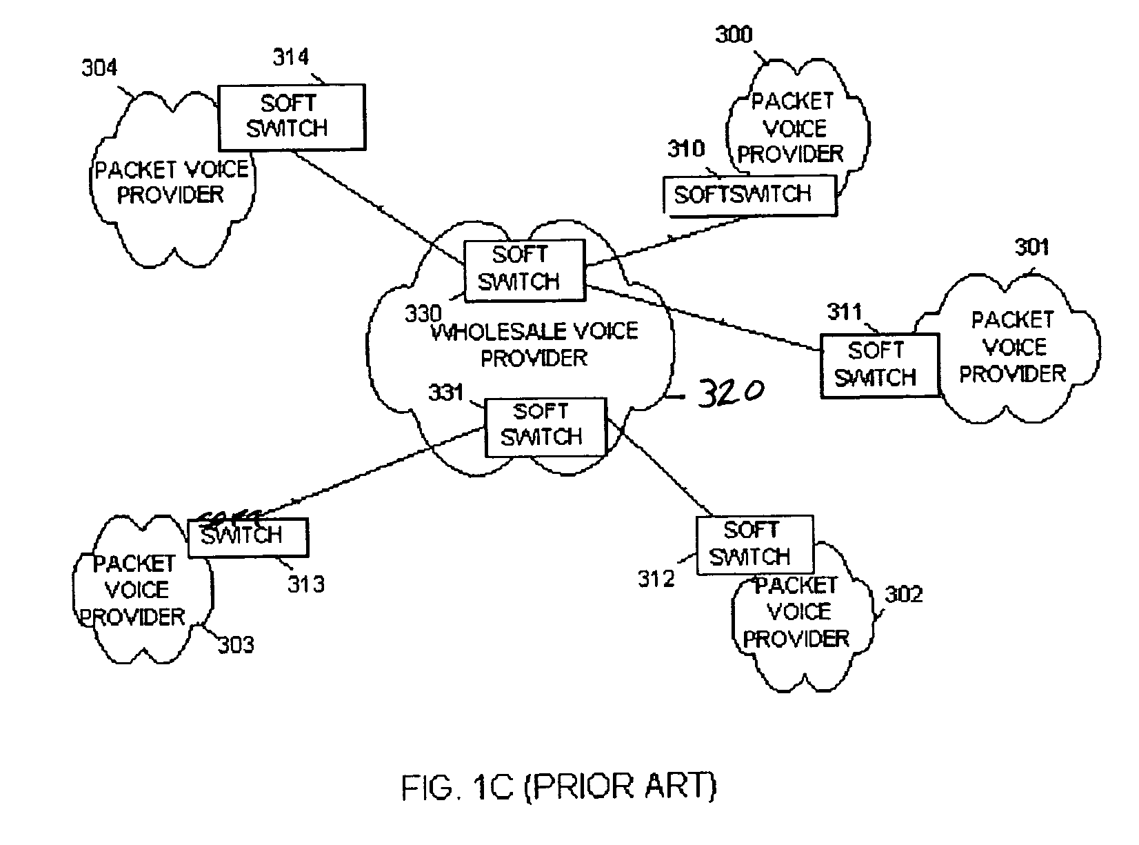
CROSS-REFERENCED TO PRIOR APPLICATIONS[0001] This application claims the benefit of U.S. Provisional Application Serial No. 60 / 412,685 filed Sep. 23, 2002.[0002] 1. Technical Field of the Invention[0003] The present invention relates to the field of telecommunications, specifically the transport and processing of optical and electrical packetized data, voice, and video. It also relates to the optimization of telecommunication resources between two or more different administrative domains.[0004] 2. Description of Related Art[0005] Service providers have been struggling to find means to reduce operational and capital expenses, and improve revenue streams. These challenges have been magnified by the explosive growth in Internet traffic resulting in an exponential demand for Internet Protocol (IP) networks and its services. This has put more pressure than ever on service providers to bring in additional revenue from their networks, reduce costs of operating the network and minimize capi...

Claims


Application Information

Patent Timeline
IPC IPC(8): H04L12/28H04L12/56
CPCH04L12/2856H04L12/2874H04L47/787H04L47/10H04L12/5695H04L47/70
Inventor NASSAR, AYMAN ESAM
Owner NASSAR AYMAN ESAM
Why Eureka
Try Eureka