Turbo pump

Inactive Publication Date: 2004-04-08
ISHIGAKI CO LTD
View PDF4 Cites 17 Cited by
  • Summary
  • Abstract
  • Description
  • Claims
  • Application Information

AI Technical Summary

Benefits of technology

0041] FIG. 9 is a graph showing performance curves of the pump according to the first embodiment.
0042] FIG. 10 is a graph showing a percent Q-H characteristic of the pump according to the first embodiment, in comparison with a conventional centrifugal pump.
0043] FIG. 11 is a graph showing a percent shaft power characteristic of the pump according to the first embodiment, in compa

Problems solved by technology

However, the axial flow type has low head, but large delivery.
It however is unable to raise the head, because cavitation occurs at high heads.
It however is unable to have a large delivery flow due to cavitation.
It however is subject to an ever smaller delivery flow due to cavitation.
The centrifugal impeller may have an increa

Method used


Image

  • Turbo pump
  • Turbo pump
  • Turbo pump

Examples


first embodiment

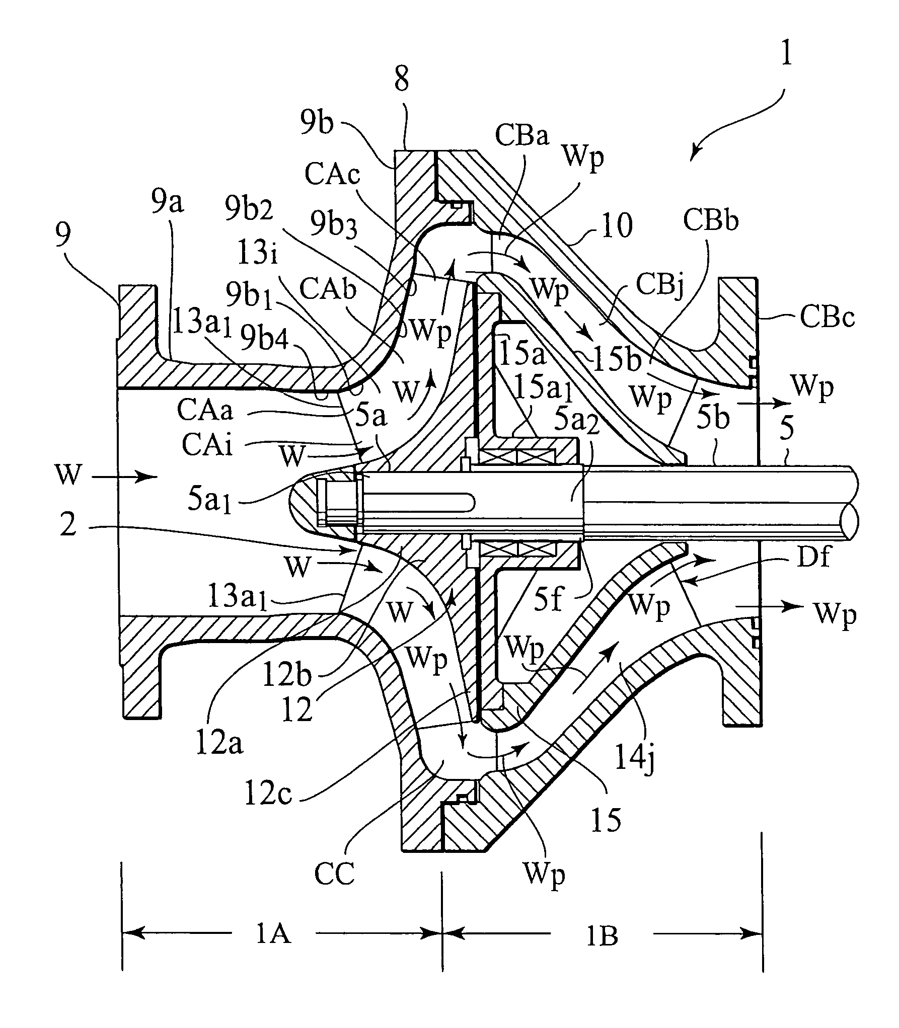
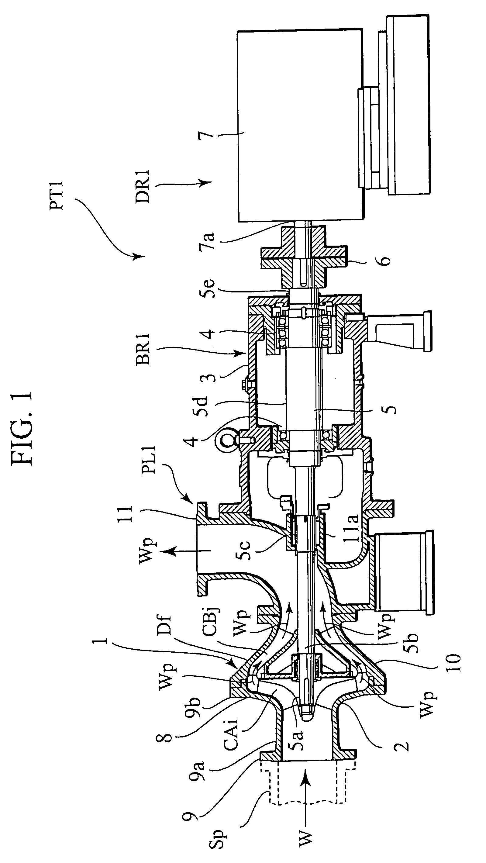
[0061] FIG. 1 shows an essential portion PT1 of a plant equipped with a single-staged horizontal shaft type turbopump 1 (hereafter called "horizontal shat pump") according to the

[0062] The plant essential portion PT1 is configured as a water pumping installation for pumping rain water W pooled at a low-depth underground, and includes an elbow-shaped water pumping line PL1, a bearing mechanism BR1 provided to the water pumping line PL1 for bearing a spindle 5 of the horizontal shat pump 1 to be horizontal, and a drive mechanism DR1 for driving the spindle 5 to rotate. The bearing mechanism BR1 is configured with a bearing box 3 having left and right bearings 4 and 4 supporting the spindle 5, at a right half 5d thereof in the figure, in a both-end supporting manner. The drive mechanism DR1 includes an externally controlled electric motor 7, and a shaft coupling 6 for fastening a right end 5e of the spindle 5 to an output shaft 7a of the motor 7.

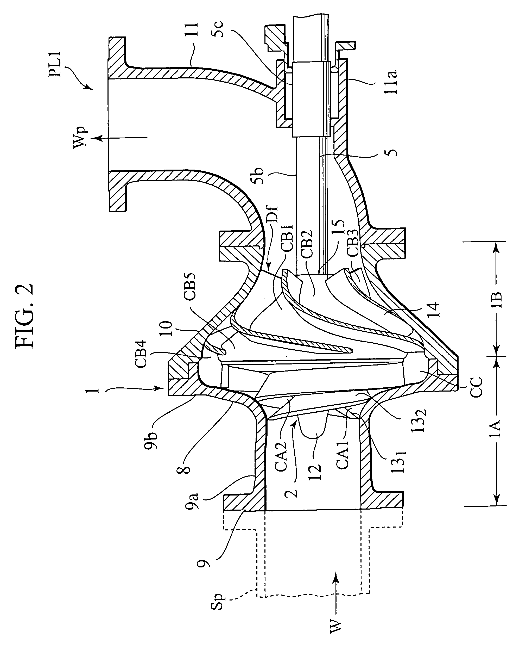
[0063] FIG. 2 shows a section of the wat...

second embodiment

[0158] FIG. 24 shows an essential portion PT2 of a plant equipped with a single-staged horizontal shaft type turbopump 16 (hereafter called "horizontal shat pump") according to the second embodiment.

[0159] The essential portion PT2 of the plant is configured as a water pumping installation for pumping rain water W pooled at a mediate-to-high-depth underground, and includes a water pumping line PL2 substantially L-shaped in side view, a bearing mechanism BR2 provided to the water pumping line PL2 for bearing a spindle 5 of the horizontal shat pump 16 to be horizontal, and a drive mechanism DR2 for driving the spindle 5 to rotate. The bearing mechanism BR2 is configured with a bearing box 3 having left and right bearings 4 and 4 supporting the spindle 5, at a right half 5d thereof in the figure, in a both-end supporting manner. The drive mechanism DR2 includes an externally controlled electric motor 7, and a coupling for fastening a right end 5e of the spindle 5 to the motor 7.

[0160] ...

third embodiment

[0164] FIG. 25 shows an essential portion PT3 of a plant equipped with a single-staged vertical shaft type turbopump 21 (hereafter called "vertical shat pump") according to the third embodiment.

[0165] The essential portion PT3 of the plant is configured as a water pumping installation for pumping rain water W pooled at a high-depth underground or in a well type water tank, and includes a water pumping line PL3 substantially I-shaped in side view, a bearing mechanism BR3 for vertically bearing an upper part 22a of a spindle 22 of the vertical shat pump 21 provided in the water pumping line PL3, and an externally controlled drive mechanism DR3 for driving the spindle 5 to rotate.

[0166] The water pumping line PL3 is configured with the vertical shaft pump 21 having a pump casing 23 fixed to a support frame, and a water sending vertical pipe 26 flange-connected to a delivery casing part 25 of the pump casing 23. The vertical pipe 26 includes an elbow 26a, which has a water sealing part ...


PUM


Abstract

In order to provide a high-head, large-delivery turbopump adapted for excellent suction performance and foreign matter passability by having characteristics of an inducer, axial flow vanes, and mixed flow vanes imparted together to centrifugal vanes, a progressively diameter-increased suction casing rear part (9b) has arranged therein an impeller (2) configured with two to four rotary vanes (13) wound around a hub (12), to define rotary channels (CA) having a vane outlet channel width (b2) of 26% in proportion to a vane inlet outer circumference diameter (d10), the rotary vanes being each respectively configured as a collision-less connection of an upstream axial-flow screw part (13a) provided with an inducer part (13a1) extending into a suction fluid path of a suction casing front part (9a) at a vane inlet angle (beta1) of 14°, an intermediate mixed-flow screw part (13b), and a downstream centrifugal screw part (13c).

Description

[0001] The present invention relates to a turbo-type pump (hereafter called "turbopump"), and in particular, to a turbopump capable of large delivery in high head conditions.[0002] As a liquid transfer machine, a pump is classifiable from the point of view of working principles into a turbopump, a positive displacement pump, and a special pump.[0003] The turbopump has a casing and a vaned rotor (called "impeller") disposed therein cooperatively defining channels for liquid to flow, and is adapted for the impeller's rotation to provide liquid in the channels with a pumping head. The head-provided liquid is called "pumped liquid".[0004] For conventional turbopumps, fundamental impeller types and typical characteristics are listed in Table-1 below.1TABLE 1 Fundamental Impeller Types and Typical Characteristics Types Centrifugal Mixed flow Axial flow Outflow direction Radial Diagonal Axial Head provider CF*.sup.1 CF*.sup.1 + VPF*.sup.2 VPF*.sup.2 Head, H High Moderate Low Delivery, Q Sm...

Claims


Application Information

Patent Timeline
IPC IPC(8): F04D1/02F04D1/04F04D29/18F04D29/22F04D29/40
CPCF04D1/025F04D1/04F04D7/04F04D29/448F04D29/2255F04D29/2277F04D29/183F04D29/22
Inventor ISHIGAKI, EIICHIYOSHIDA, TOMOKI
Owner ISHIGAKI CO LTD
Why Eureka
Try Eureka