Clamping screw extractor

a screw extractor and screw technology, applied in the field of mechanical fasteners and devices, can solve the problems of difficult to determine whether a particular screw is the source of neurological symptoms experienced by patients, surgeons are unable to fully visualize the structures involved, and achieve the ideal result not always achieved

Inactive Publication Date: 2004-04-08
MEDITRON DEVICES
View PDF11 Cites 121 Cited by
  • Summary
  • Abstract
  • Description
  • Claims
  • Application Information

AI Technical Summary

Benefits of technology

0015] The present invention comprises a tool for gripping and removing mechanical fasteners such as pedicle screws. With reference to FIG. 7, the device generally resembles a screwdriver, having a handle on one end, a long shaft in the middle, and fastener engaging means on the other end. The fastener engaging means comprises a set of two or more jaws having inward facing gripping surfaces positioned to grasp the external surfaces of a screw head. The jaws are formed as part of a collet sidably mounted within an outer thread sleeve. The thread sleeve is attached to the shaft.
0016] A tapered journal on the collet interacts with a tapered bore in the thread sleeve so that when the collet is pulled into the thread sleeve, the set of two or more jaws are squeezed together. The threaded engagements between the collet and the thread sleeve should be the reverse of the thread on the screw to be removed; i.e., if a right-hand screw is to be removed then the threaded engagement between the collet and the thread sleeve should be made with a left-hand thread. In operation, the jaws are placed over the screw head and the device is rotated in a counterclockwise direction (for removal of a screw with a right-hand thread). The inward facing surfaces on the jaws bear against the bolt head, thereby impeding the rotation of the collet relative to the thread sleeve. The left-hand threaded engagement between the collet and the thread sleeve therefore pulls the collet further into the thread sleeve, whereupon the tapered bore squeezes the jaws more tightly together. Thus, the reader will appreciate, applying torque to the device when it is in position on a screw head simultaneously torques the screw head and squeezes the jaws more tightly together. The inward facing surfaces are also provided with an undercut in order to accommodate axial misalignment between the jaws and the screw head.

Problems solved by technology

The ideal result is not always achieved, however.
They will also know that the surgeon is unable to fully visualize the structures involved.
These factors may lead to imperfect results.
It is often difficult to determine whether a particular pedicle screw is the source of the neurological symptoms experienced by the patient.
As the patient is asleep during the procedure, there is no way to determine if the removal of the screw altered the symptoms until much later.

Method used


Image

  • Clamping screw extractor
  • Clamping screw extractor
  • Clamping screw extractor

Examples


Embodiment Construction

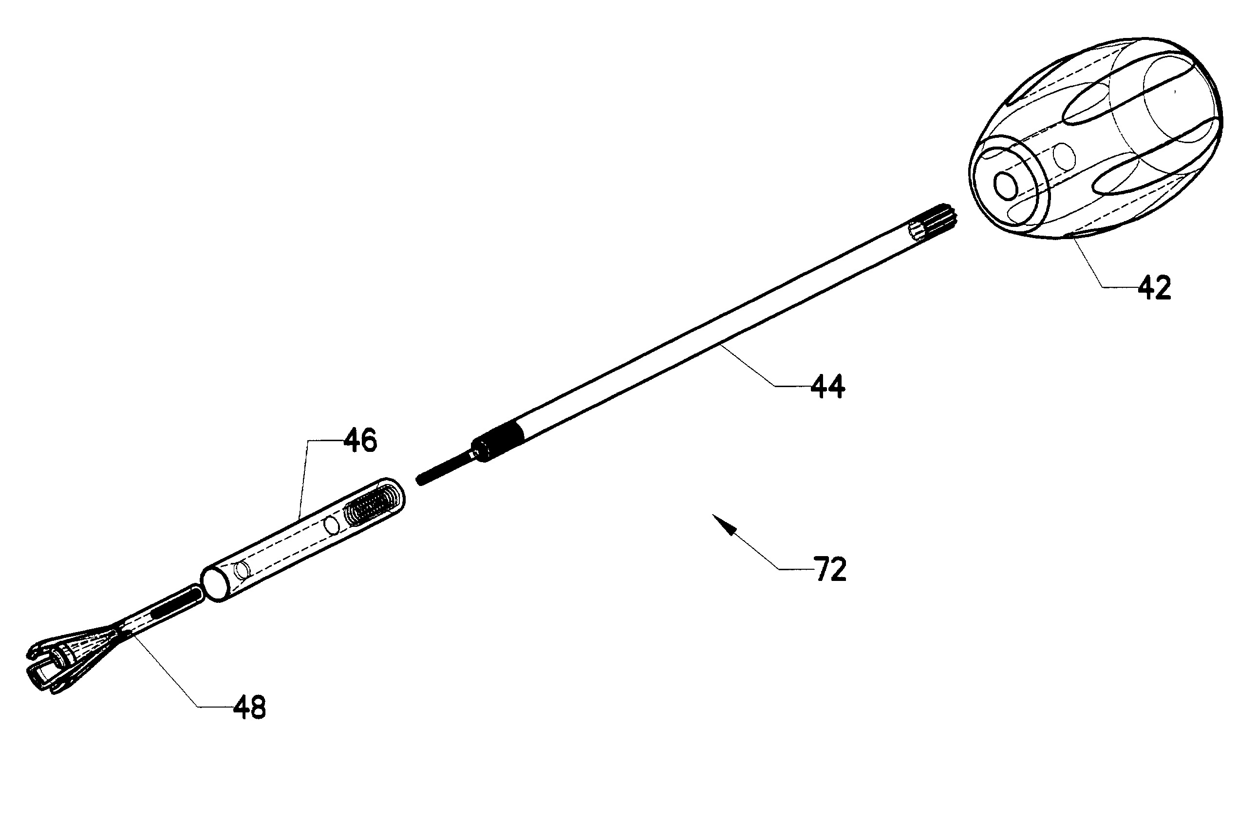
[0041] The present invention is a screw extraction tool capable of accessing and removing a screw in a confined space. In order to understand the operation of the extraction tool, it is helpful to understand the operative environment in which it functions.

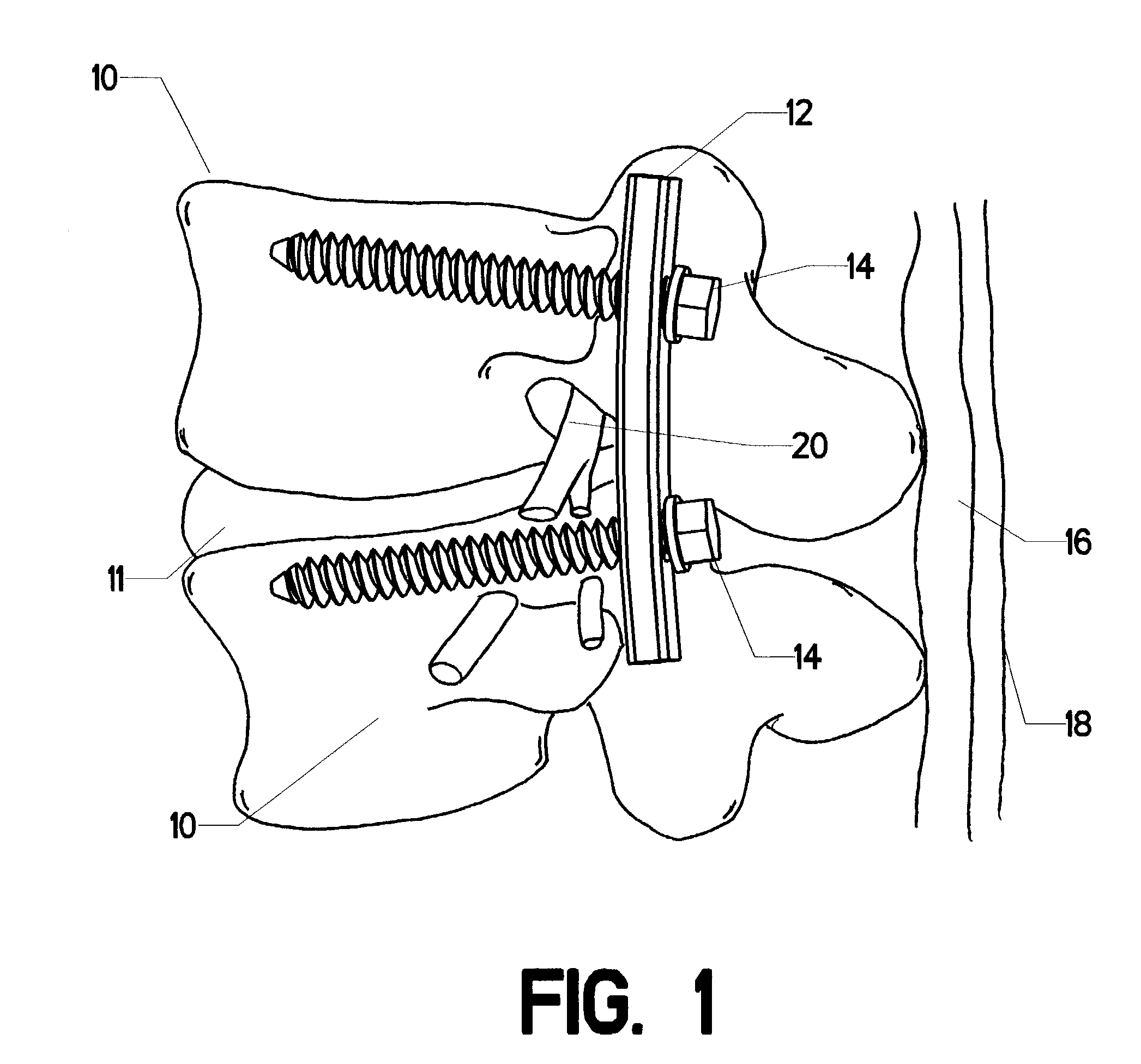
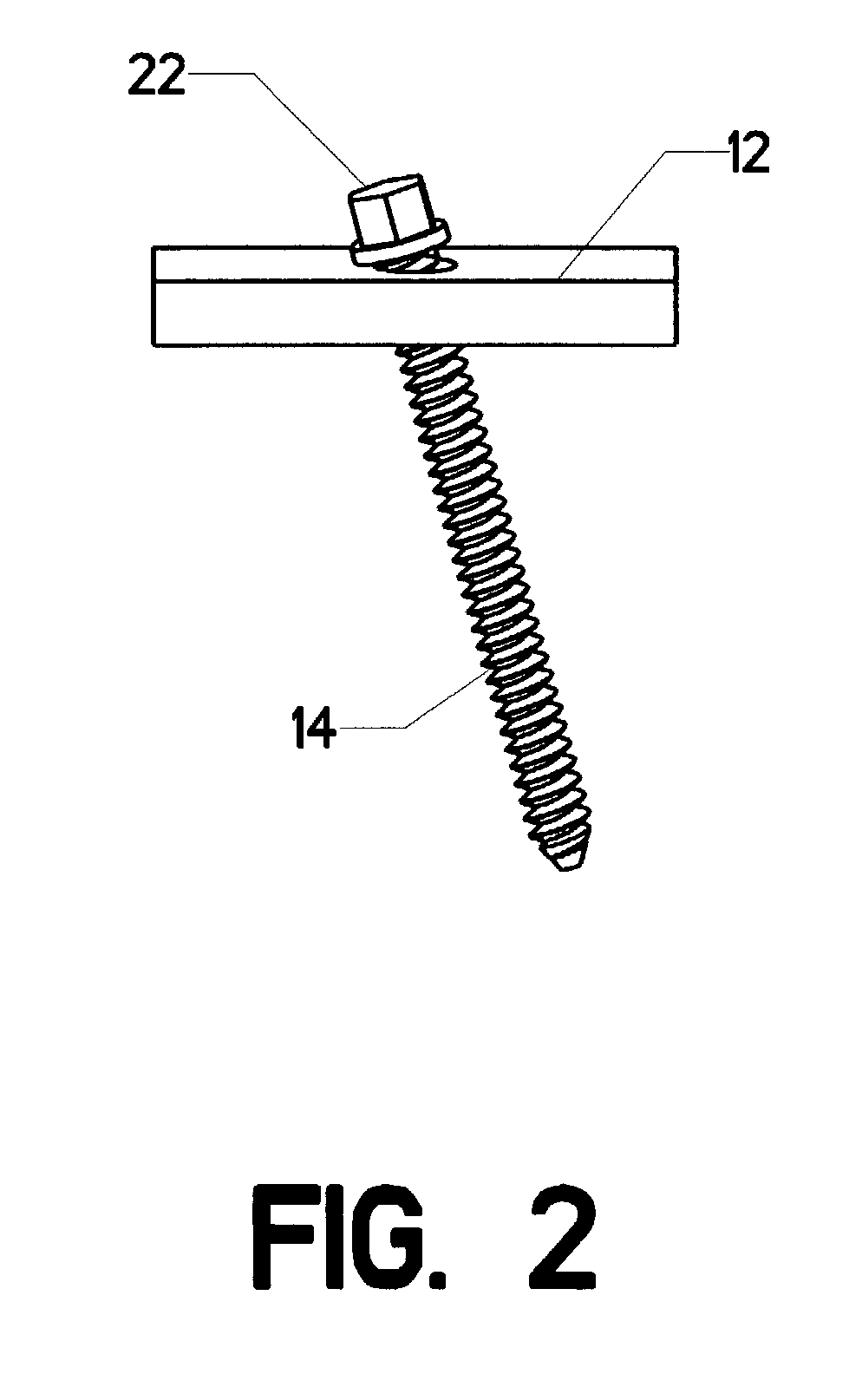
[0042] Returning now to FIG. 1, the objective for which the invention was primarily designed is the removal of one or more pedicle screws 14. Radiographic techniques are used to locate the suspicious pedicle screw. Turning now to FIG. 3, small incision 24 is made directly over the pedicle screw. A guide wire 84 is then placed on the screw head, with its free end extending out of the incision as shown.

[0043] Turning now to FIG. 4, first dilater tube 26 is placed in the incision by slipping it along the guide wire. First dilater tube 26 is a hollow tube having an inner diameter greater than the guide wire. By inserting it into the incision along the guide wire, the incision is dilated slightly. Next, a succession of dilator tubes, ea...


PUM


Abstract

A tool for gripping and removing mechanical fasteners such as pedicle screws. With reference to FIG. 7, the device generally resembles a screwdriver, having a handle on one end, a long shaft in the middle, and fastener engaging means on the other end. The fastener engaging means comprises a set of two or more jaws having inward facing gripping surfaces positioned to grasp the external surfaces of a screw head. The jaws are formed as part of a collet slidably mounted within an outer thread sleeve. The thread sleeve is attached to the shaft. A tapered journal on the collet interacts with a tapered bore in the thread sleeve so that when the collet is pulled into the thread sleeve, the set of two or more jaws are squeezed together. The threaded engagements between the collet and the thread sleeve should be the reverse of the thread on the screw to be removed; i.e., if a right-hand screw is to be removed then the threaded engagement between the collet and the thread sleeve should be made with a left-hand thread. In operation, the jaws are placed over the screw head and the device is rotated in a counterclockwise direction (for removal of a screw with a right-hand thread). The inward facing surfaces on the jaws bear against the bolt head, thereby impeding the rotation of the collet relative to the thread sleeve. The left-hand threaded engagement between the collet and the thread sleeve therefore pulls the collet further into the thread sleeve, whereupon the tapered bore squeezes the jaws more tightly together. Thus, the reader will appreciate, applying torque to the device when it is in position on a screw head simultaneously torques the screw head and squeezes the jaws more tightly together. The inward facing surfaces are also provided with an undercut in order to accommodate axial misalignment between the jaws and the screw head.

Description

CROSS-REFERENCES TO RELATED APPLICATIONS[0001] Not applicable.[0002] Not Applicable.MICROFICHE APPENDIX[0003] Not Applicable[0004] 1. Field of the Invention[0005] This invention relates to the field of mechanical fasteners and devices for their removal. More specifically, the invention comprises a screw extractor configured to remove screws such as pedicle screws and similar orthopaedic hardware. Although the invention was developed for use in the field of medicine, those skilled in the art will realize that it has application in many other fields.[0006] 2. Description of the Related Art[0007] The field of orthopaedic medicine involves the application of plates and screws to stabilize compromised articulations in the human body. One typical application is stabilization of the lumbar vertebrae after collapse of one or more intervertebral disks. FIG. 1 is an illustration of two lumbar vertebrae 10. Intervertebral disk 11 lies between the two. In this example, instability of the spine ...

Claims


Application Information

Patent Timeline
Patent Type & Authority Applications(United States)
IPC IPC(8): A61B17/88
CPCY10T279/17299A61B17/8891
Inventor BONATI, ALFRED O.WARE, PHILIP J.
Owner MEDITRON DEVICES
Why Eureka
Try Eureka