
Exhaust heat utilization system, exhaust heat utilization method, and semiconductor production facility

Inactive Publication Date: 2004-04-15
TOKYO ELECTRON LTD +1
View PDF0 Cites 12 Cited by
  • Summary
  • Abstract
  • Description
  • Claims
  • Application Information

AI Technical Summary

Benefits of technology

[0011] A more specific object of the present invention is to provide an exhaust-heat utilization system and exhaust-heat utilization method which can achieve energy saving of semiconductor manufacturing facilities by reusing a warmed cooling-water, as a heating source, exhausted from semiconductor manufacturing apparatuses.
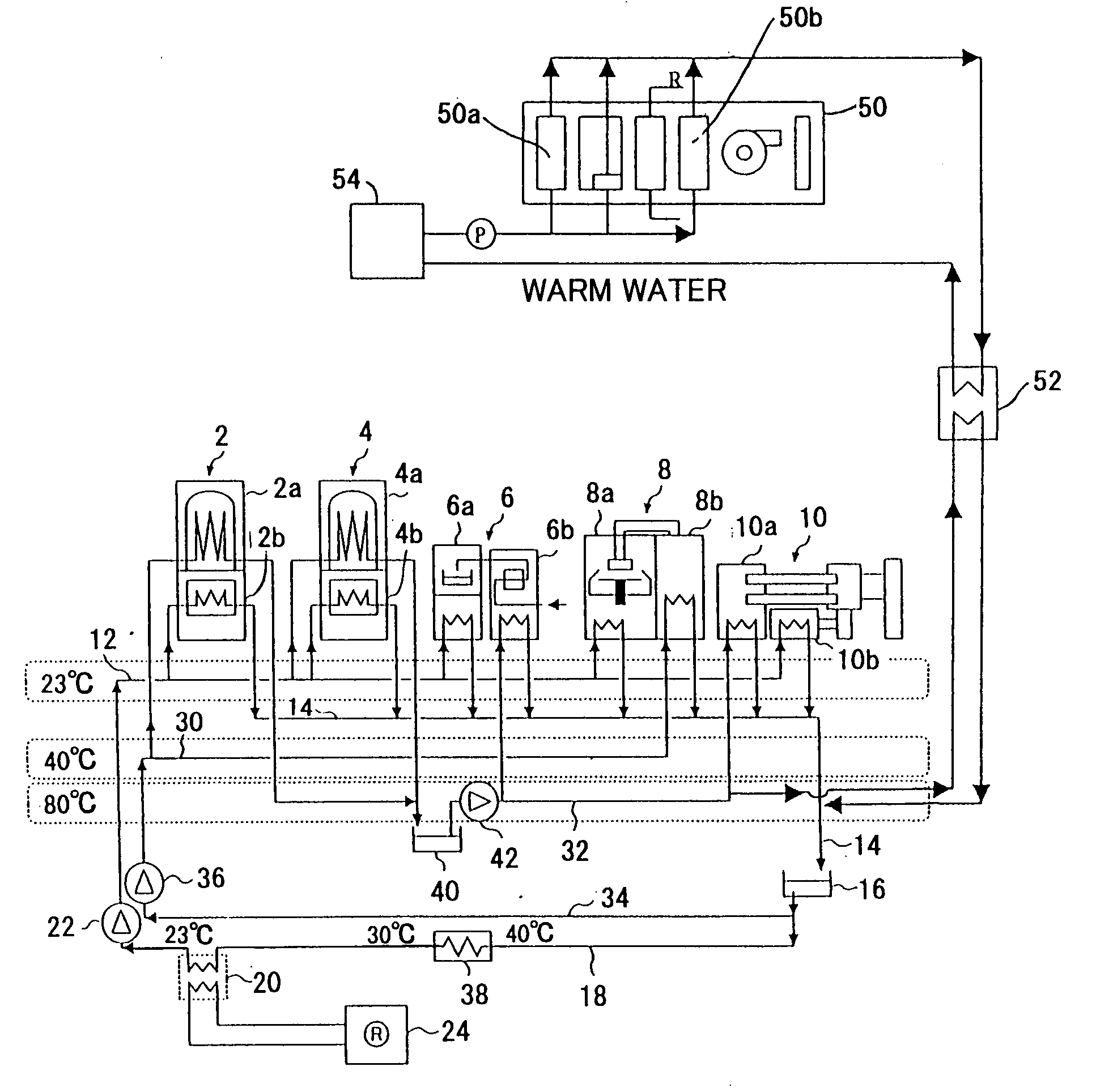
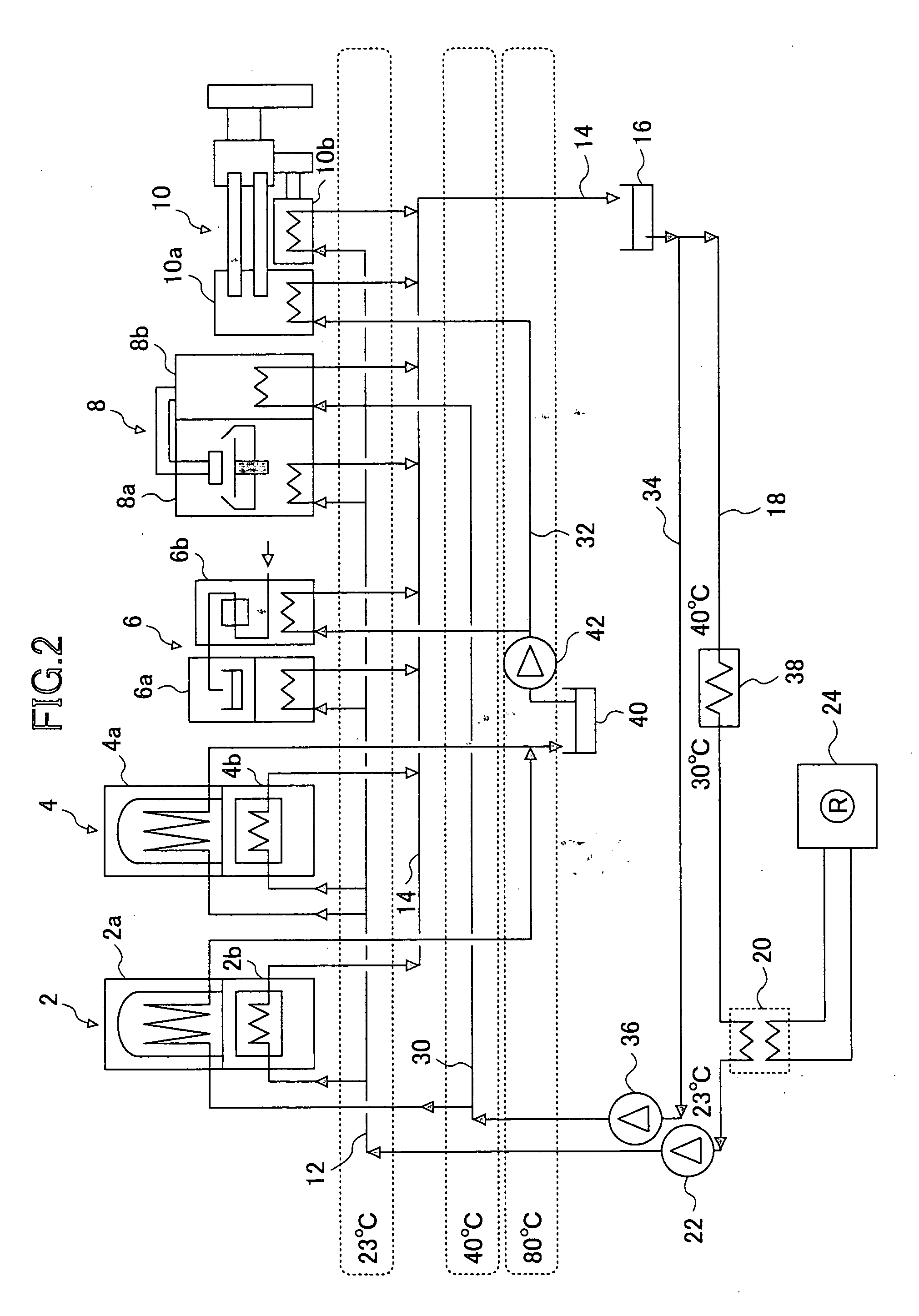
[0021] According to above-mentioned invention, a part of the medium-temperature cooling-water exhausted from each semiconductor manufacturing apparatus can be supplied to a part of the semiconductor manufacturing apparatus that requires a heating process, and, thus, the heat conventionally discarded through the cooling water can be reused. Additionally, only the high-temperature cooling-water exhausted from a predetermined semiconductor manufacturing apparatus is recovered and used as a heating source of other semiconductor manufacturing apparatuses, and the heat of the cooling water can be reused for a heating process which requires a heating temperature higher than the temperature of the medium-temperature cooling-water. Thus, since a part of heat of the warmed cooling-water exhausted from the semiconductor manufacturing apparatuses, which heat was conventionally discarded by the cooling apparatus through the heat exchanger, is reused for the heating process of other semiconductor manufacturing apparatuses, energy saving of the whole semiconductor manufacturing facility can be attained.
[0024] According to the above-mentioned invention, the warmed cooling water which is exhausted from a semiconductor manufacturing apparatus can be reused as a heating source of the outside-air conditioning unit that consumes large energy as a heat source, and the energy consumption by the whole semiconductor plant can be greatly reduced.

Problems solved by technology

ge. Therefore, the facility cost of the cooling apparatus 24 is very high, and the running cost of the cooling apparatus 24 is also increa

Method used


Image

  • Exhaust heat utilization system, exhaust heat utilization method, and semiconductor production facility
  • Exhaust heat utilization system, exhaust heat utilization method, and semiconductor production facility
  • Exhaust heat utilization system, exhaust heat utilization method, and semiconductor production facility

Examples


Embodiment Construction

[0029] A description will now be given, with reference to the drawings, of an embodiment of the present invention.

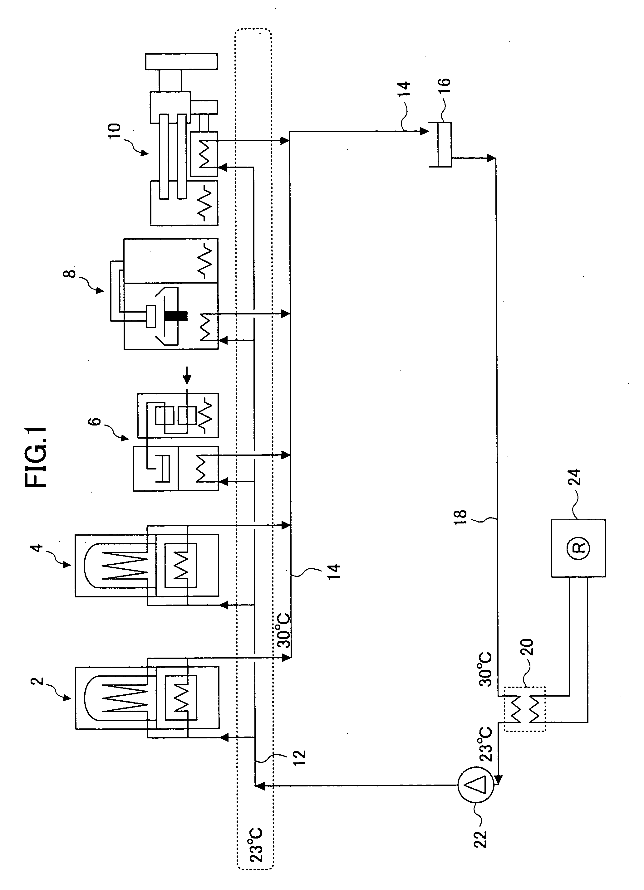
[0030] FIG. 2 is an illustration of a structure of an exhaust-heat utilization system according to the embodiment of the present invention. In FIG. 2, parts that are the same as the parts shown in FIG. 1 are given the same reference numerals, and descriptions thereof will be omitted.

[0031] First, the basic concept of the exhaust-heat utilization system according to the embodiment of the present invention is explained. The exhaust-heat utilization system of the present invention is one that reuses a cooling water exhausted from each semiconductor manufacturing apparatus as a heating source or a cooling source required by other semiconductor manufacturing apparatuses. That is, the cooling water exhausted from a semiconductor manufacturing apparatus from among semiconductor manufacturing apparatuses in a semiconductor manufacturing facility is reused as a relatively low-tem...


PUM


Abstract

An exhaust-heat utilization system is constructed which can achieve energy saving of semiconductor manufacturing facilities by reusing a warmed cooling-water, as a heating source, exhausted from semiconductor manufacturing apparatuses. Supply a low-temperature cooling-water having a temperature substantially equal to a room temperature to the semiconductor manufacturing apparatuses (2, 4, 6, 8, 10) through a low-temperature cooling-water line (12). Supply a medium-temperature cooling-water to the semiconductor manufacturing apparatus (8) through a medium-temperature cooling-water supply line (30), the medium-temperature cooling-water being exhausted from the semiconductor manufacturing apparatuses and having a temperature higher than the room temperature. Supply, as a heating source, a high-temperature cooling-water to a the semiconductor apparatuses (6, 10) through a high-temperature cooling-water supply line (32), the high-temperature cooling-water exhausted from the semiconductor manufacturing apparatuses (2, 4) and having a temperature still higher than the medium-temperature cooling-water.

Description

[0001] The present invention relates to exhaust-heat utilization systems and exhaust-heat utilization methods of semiconductor manufacturing-facilities and semiconductor manufacturing facilities and, more particularly, to an exhaust-heat utilization system and an exhaust-heat utilization method that reuse a cooling water, which is discharged from various kinds of semiconductor manufacturing apparatuses, for cooling or heating in other semiconductor manufacturing apparatuses, and a semiconductor manufacturing facility having such an exhaust-heat utilization system.[0002] Semiconductor manufacturing apparatuses used in semiconductor manufacturing facilities and peripheral apparatuses thereof require cooling for controlling a temperature rise of the apparatuses. Additionally, among these apparatuses, there are apparatuses that require cooling in a semiconductor manufacturing process. On the other hand, among these apparatuses, there are apparatuses that require a heating process in a s...

Claims


Application Information

Patent Timeline
IPC IPC(8): F24D3/02F24D11/02H01L21/00
CPCF24D3/02F24D11/0235F24D2200/16Y02B30/52Y02B10/70Y02B30/126H01L21/67109Y02P70/50Y02P80/10F25B27/02
Inventor SUENAGA, OSAMUKOBAYASHI, SADAOMORI, NAOKIITO, HIROMU
Owner TOKYO ELECTRON LTD
Learn More