
Method and system for delivery of therapeutic gas to a patient and for filling a cylinder

a technology for therapeutic gas and cylinders, applied in the direction of valves, container filling under pressure, operating means/releasing devices, etc., can solve the problems of limited volume of portable cylinders, harmful gases, and other problems, and achieve the effect of reducing the risk of gas leakage, and reducing the safety of patients

Inactive Publication Date: 2004-04-29
RESPIRONICS +1
View PDF46 Cites 54 Cited by
  • Summary
  • Abstract
  • Description
  • Claims
  • Application Information

AI Technical Summary

Benefits of technology

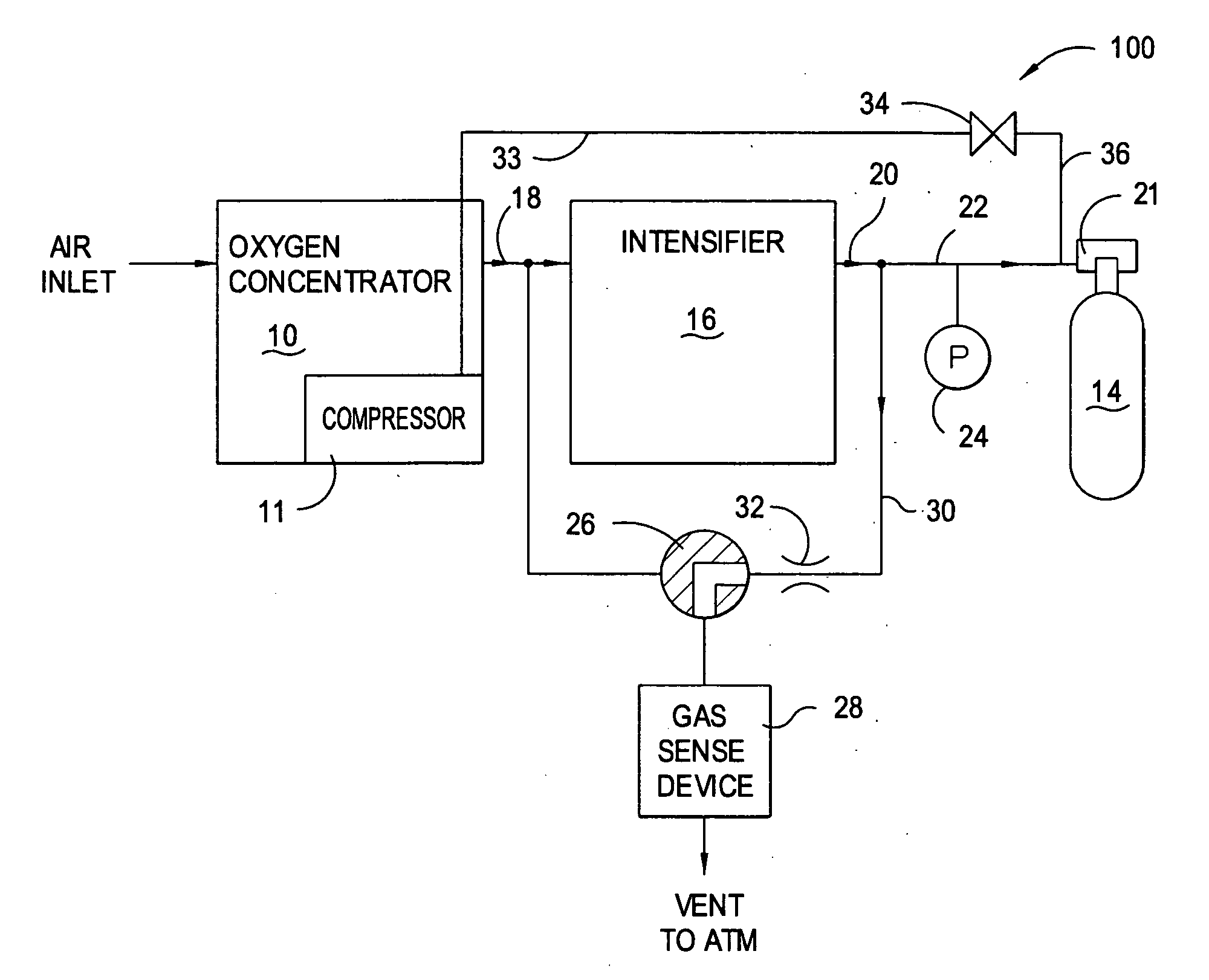
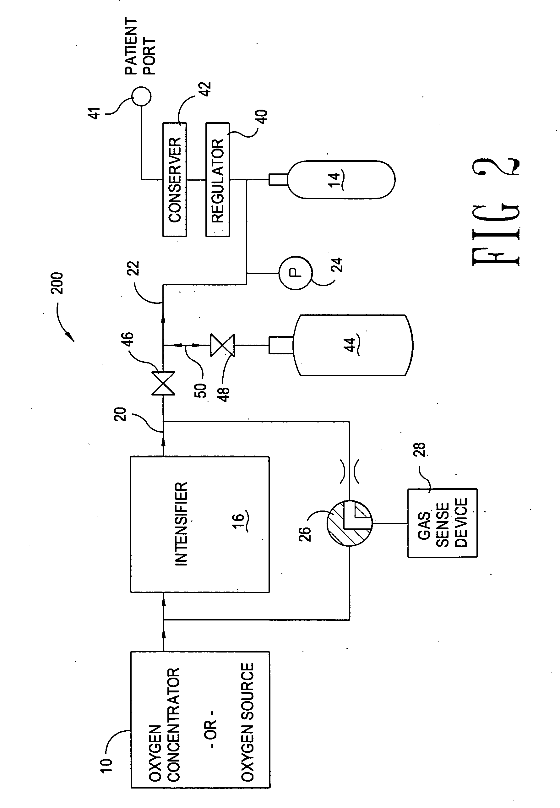
[0038] Having a cylinder 44 with a volume larger than that of the portable cylinder 14 also provides the capability for the trans-fill system 200 to have a quick-fill feature for the portable cylinder 14. Assume for purposes of explanation that valve 48 is closed and that the internal cylinder 44 is full or substantially full. To fill the portable cylinder 14, the patient may select that the oxygen concentrator and intensifier fill the portable cylinder 14. Filling using the therapeutic gas exiting the intensifier may be relatively slow, e.g. 2 liters per minute. The patient may also select a quick-fill, where the therapeutic gas provided to the cylinder 14 may come solely from the cylinder 44, or possibly from a combination of the oxygen concentrator and intensifier 16 and the cylinder 44. Operation under either of these two circumstances may provide for a faster fill of the portable cylinder 14 than may be achieved without the cylinder 44 contributing therapeutic gas.
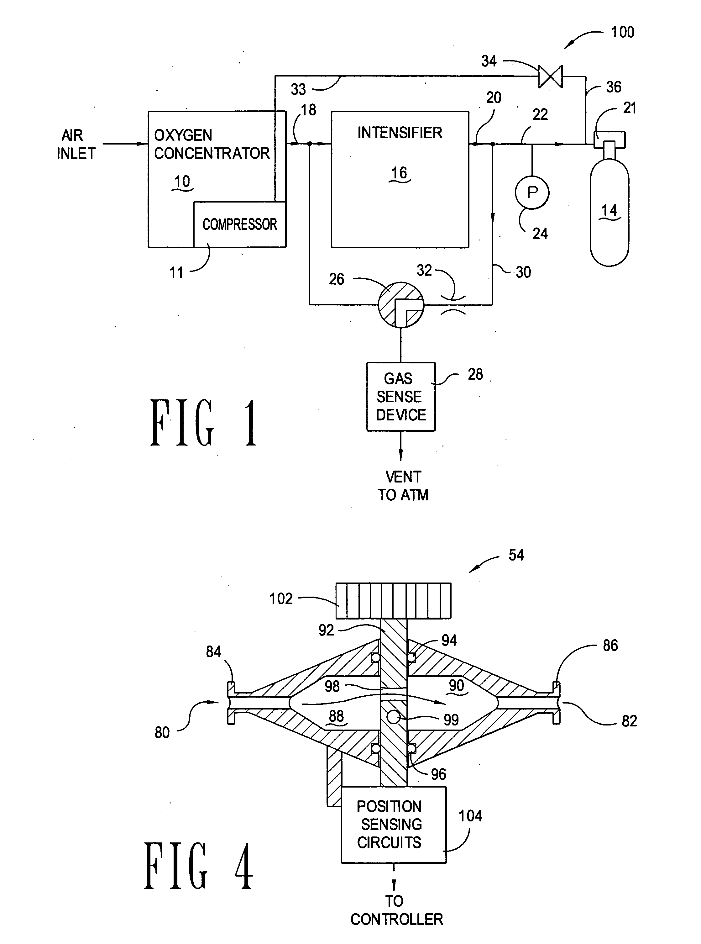
[0040] Thus, embodiments such as illustrated in FIG. 3 may have two modes of operation: a continuous flow mode where the user may select the volume of flow; and a delivery through the conserver, which may provide a bolus of therapeutic gas during inhalation. Although it may be possible to independently set the continuous flow rate of the flow meter and the bolus delivery of the conserver 42, in accordance with at least some embodiments of the invention the continuous flow setting of the flow meter may be read by a controller 56. The controller 56, determining or sensing the desired continuous flow rate, may set the conserver flow based on the continuous flow. For example, the controller 56 may set the conserver to provide a 16.5 milli-liter bolus for every liter per minute of continuous flow set by the patient. Thus, for a 2 liter-per-minute continuous flow, the controller may set the conserver to deliver a 33 milli-liter bolus of therapeutic gas, possibly at the beginning of each inhalation. In this way, the patient may only need to make one flow setting.
[0045] FIG. 3 also illustrates that the gas sense device 28 need not necessarily couple as illustrated in FIGS. 1 and 2. In particular, the gas sense device 28 may be fluidly coupled to the therapeutic gas downstream of the flow meter 54, which coupling point is also downstream of the conserver 42. While it is possible for the gas sense device 28 to operate continuously, in accordance with at least some embodiments of the invention, the gas sense device 28, when sensing therapeutic gas provided by the oxygen concentrator 10 or exiting the intensifier 16, preferably samples the gas approximately every ten minutes. Operating the gas sense device 28 every ten minutes may extend the life of various components of the gas sense device 28, and in particular may extend the life of oxygen selective sensors such as the zirconium oxide technologies. With the gas sense device 28 coupled as illustrated in FIG. 3, while supplying therapeutic gas to the patient port 41 through conserver 42 there may be insufficient flow for analysis. Thus, in these embodiments the system 300 may either: momentarily switch to a continuous flow mode (by positioning of valve 42) to allow sufficient flow for the gas sense device 28 to operate; or by increasing the bolus size from conserver 42 for sufficient time to allow the gas sense device 28 to operate.

Problems solved by technology

A portable cylinder may, however, provide only limited volume, and therefore will periodically need to be refilled.
However, the Litton patent discloses only monitoring oxygen content of the enriched gas exiting the PSA system, and situations where the oxygen content may be correct but the enriched gas product contains other harmful chemicals and / or gases may not be detected.
The Todd patent also mentions the use of an oxygen sensor to test the enriched gas from the oxygen concentrator provided to the patient, but fails to discuss the possibility that while oxygen concentration levels may be correct, other, harmful, gases may be present.

Method used


Image

  • Method and system for delivery of therapeutic gas to a patient and for filling a cylinder
  • Method and system for delivery of therapeutic gas to a patient and for filling a cylinder
  • Method and system for delivery of therapeutic gas to a patient and for filling a cylinder

Examples


Embodiment Construction

[0011] The problems noted above are solved in large part by a method and system for delivery of therapeutic gas to a patient and for filling of a cylinder. One exemplary embodiment may be a trans-fill system that comprises an intensifier (operable to increase pressure of therapeutic gas provided at an inlet of the intensifier to create a compressed therapeutic gas stream), a conserver coupled to the compressed therapeutic gas stream (operable to deliver a bolus of therapeutic gas during inhalation of the patient), a patient port coupled to the conserver (operable to provide the bolus of therapeutic gas to the patient), and a cylinder connector (operable to couple a portable cylinder to the compressed therapeutic gas stream). The trans-fill system itself may be operable to provide therapeutic gas to the cylinder connector to fill the portable cylinder while providing therapeutic gas to the patient through the conserver.

[0012] In other exemplary embodiments, contents of the connected ...


PUM


Abstract

A system for filling a portable cylinder with therapeutic gas, and providing therapeutic gas to a patient. Therapeutic gas delivery to a patient may be through a conserver, or may be in a continuous mode. Some embodiments of the invention may test the contents of the portable cylinder prior to filling. The specification also discloses a silent mode of operation where therapeutic gas is provided from the system by means of internal and / or external cylinders.

Description

[0001] This application claims the benefit of provisional application Serial No. 60 / 421,375 filed Oct. 24, 2002, which application is incorporated by reference herein as if reproduced in full below.[0002] Not applicable.[0003] 1. Field of the Invention[0004] Embodiments of the present invention are directed to creation of therapeutic gas, possibly for delivery to a patient for respiratory use. More particularly, embodiments of the invention are directed to systems for creation of therapeutic gas for delivery to a patient and for filling portable cylinders for ambulatory use.[0005] 2. Background of the Invention[0006] Many patients with lung and / or cardiovascular problems may be required to breathe therapeutic gas in order to obtain sufficient dissolved oxygen in their blood stream. So that these patients may be ambulatory, therapeutic gas may be delivered from a portable cylinder. A portable cylinder may, however, provide only limited volume, and therefore will periodically need to ...

Claims


Application Information

Patent Timeline
Patent Type & Authority Applications(United States)
IPC IPC(8): A61M16/00A61M16/10F17C5/00
CPCA61M16/10F17C2270/025F17C5/002A61M16/101F17C2201/0109F17C2201/058F17C2205/0329F17C2205/0335F17C2205/0338F17C2205/0341F17C2221/011F17C2221/031F17C2223/0123F17C2223/033F17C2227/0157F17C2227/04F17C2227/045F17C2250/0443F17C2250/0452F17C2250/0636F17C2250/0647A61M2016/0039A61M2202/0208A61M2202/03A61M2202/0007
Inventor AYLSWORTH, ALONZO C.SPECTOR, LAWRENCE C.
Owner RESPIRONICS
Learn More