2-D actuator and manufacturing method thereof

a technology of actuators and actuators, applied in the direction of soldering devices, instruments, photomechanical devices, etc., can solve the problems of limited application range of conventional actuators, limited effective area of optical scanning stages, and inability to drive linearly

Inactive Publication Date: 2004-04-29
SAMSUNG ELECTRONICS CO LTD
View PDF12 Cites 47 Cited by
  • Summary
  • Abstract
  • Description
  • Claims
  • Application Information

AI Technical Summary

Problems solved by technology

As a result, the conventional actuator is limited in its application.
Thus, the arrangement structure of the comb electrodes as in the first axis driving actuator greatly limits an effective area of a stage for optical scanning.
Also, since the above bi-axes driving actuator is a resonant scanner which moves continuously, a static mirror positioning is not possible so that a linear driving is impossible.
Also, since the driving comb electrode and the stationary comb electrode are arranged on a plane such as a stage or a frame, a symmetrical electric field is generated between the driving comb electrode and the stationary comb electrode so that a driving force to induce driving of the stage cannot be obtained.
Also, since one stage is provided at one scanner, the bi-axes driving actuator is difficult to be applied to a laser television requiring a reflection surface of a sufficient size.

Method used


Image

  • 2-D actuator and manufacturing method thereof
  • 2-D actuator and manufacturing method thereof
  • 2-D actuator and manufacturing method thereof

Examples


embodiment 2

[0049] A second preferred embodiment 2 described below is related to an actuator where a plurality of stages are arranged in an array form.

embodimente 2

PREFERRED EMBODIMENTE 2

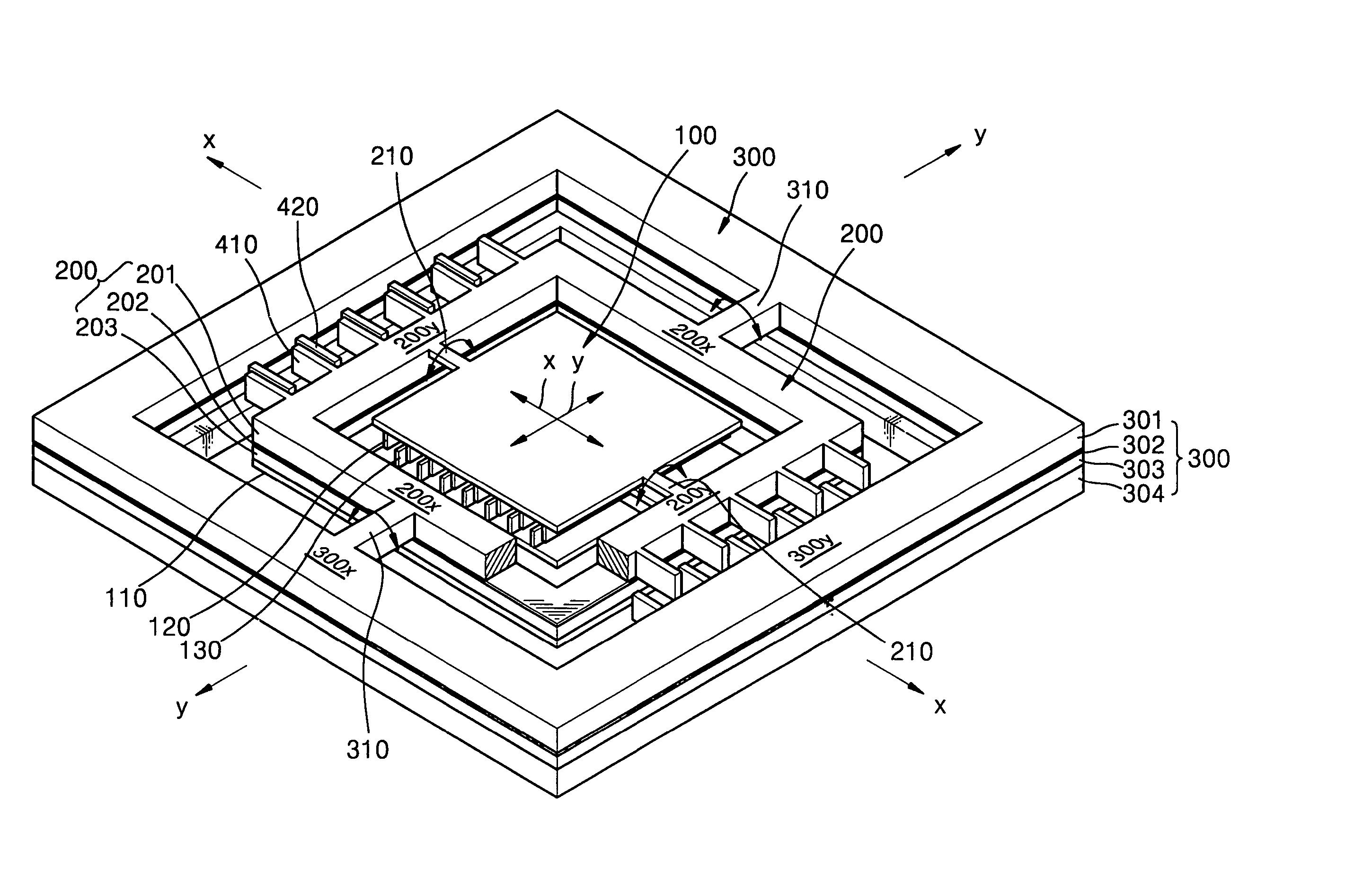
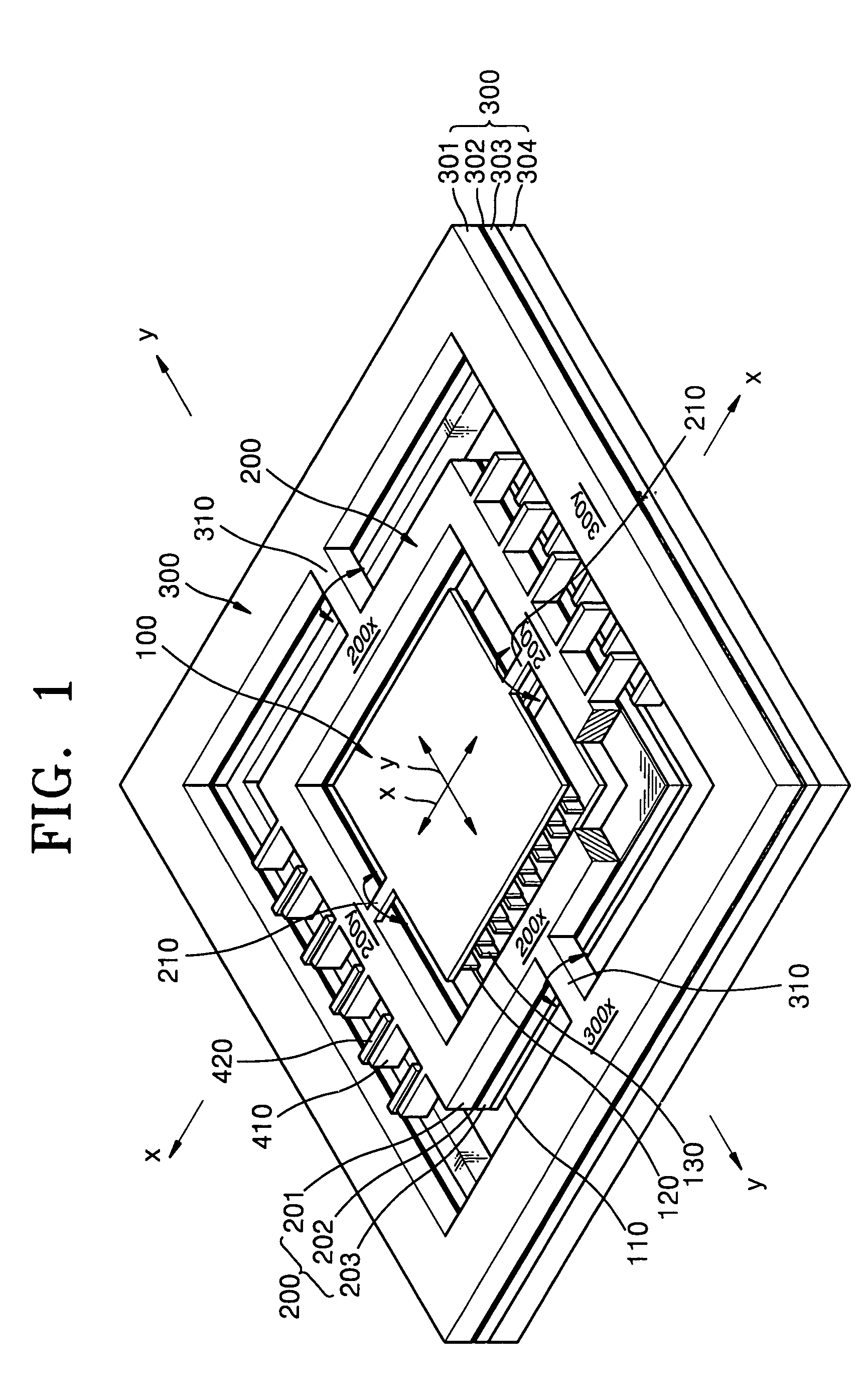
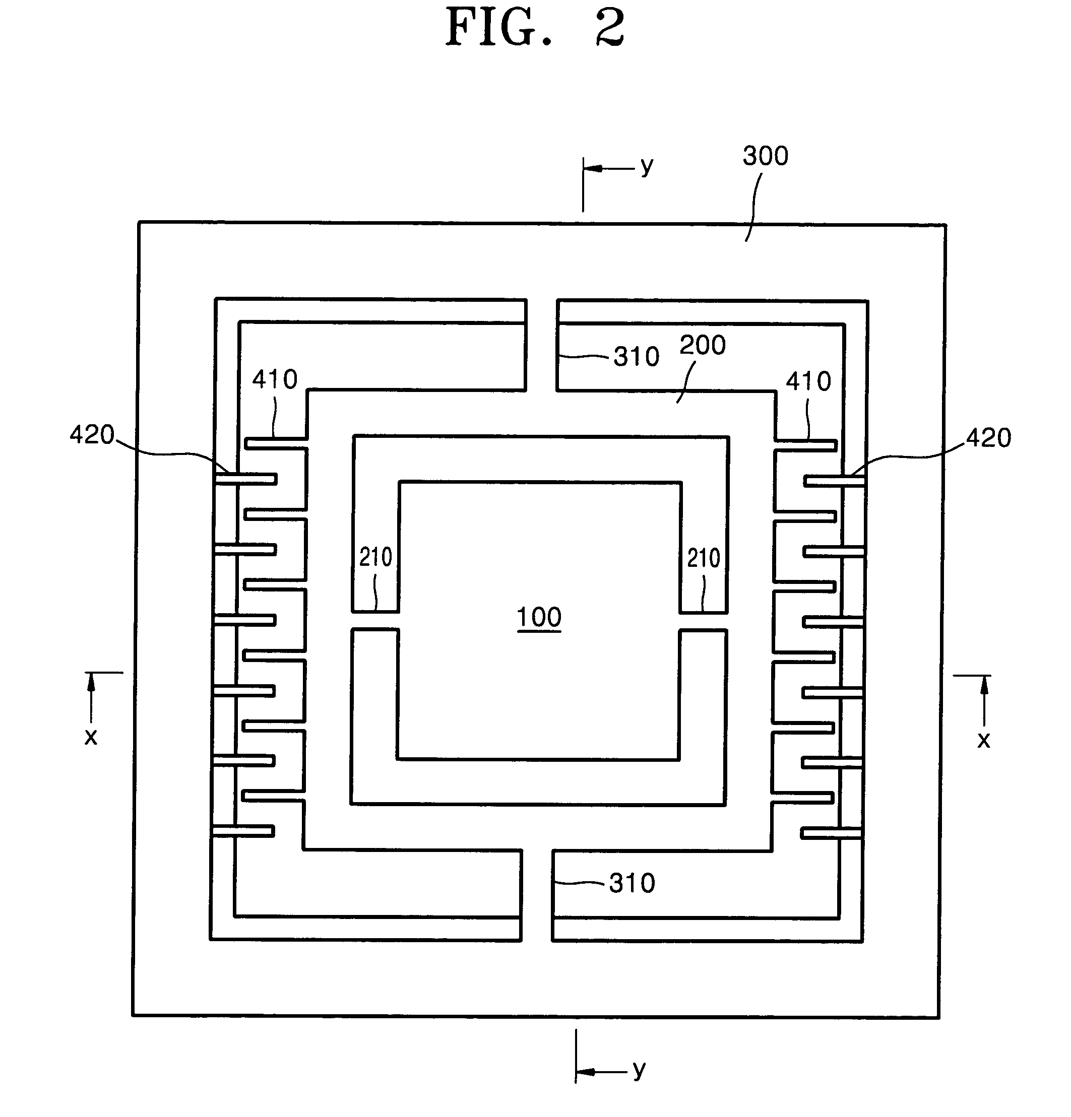
[0050] FIG. 5 is a perspective view illustrating an actuator according to the present invention having an improved structure. FIG. 6 is a plan view of the actuator of FIG. 5. FIG. 7 is a sectional view taken along line x-x of FIG. 6.

[0051] Referring to FIGS. 5 and 6, a plurality of stages 100a where a mirror (not shown) is formed on a surface thereof are arranged in an array form and the stage array is encompassed by the rectangular edge type movable frame 200. A first torsion bar 210a constituting a first support portion with the rectangular edge type movable frame 200 is extended from both ends of each of the stages 100a. Thus, the stages 100a are supported by the first support portion capable of seesawing with respect to center axes x.sub.0-x.sub.0, . . . ,x.sub.n-x.sub.n parallel to the first direction, respectively. Also, as described in the above first preferred embodiment, the first support portion supporting the stages 100a is supported by a second sup...


PUM

PropertyMeasurementUnit
thicknessaaaaaaaaaa
thicknessaaaaaaaaaa
thicknessaaaaaaaaaa

Abstract

An actuator includes a stage having a first direction and a second direction perpendicular to the first direction and seesawing around a third direction perpendicular to the first direction and the second direction with respect to a rotation center axis placed along the first direction. A first support portion supports a seesaw motion of the stage. A base facing the stage under the stage at a predetermined interval is supported by the first support portion. A stage driving portion has a plurality of first driving comb electrodes and a plurality of first stationary comb electrodes corresponding to the first driving comb electrodes which are respectively formed on a lower surface of each of the stages and an upper surface of the base facing the stages. A second support portion supports the first support portion so that the first support portion seesaws with respect to a rotation center axis placed along the second direction. A first support portion driving portion has a second driving comb electrode provided at the first support portion and a second stationary comb electrode fixedly positioned to correspond to the second driving comb electrode to generate a seesaw motion of the first support portion.

Description

[0001] This application claims the priority of Korean Patent Application No. 2002-63853 filed on Oct. 18, 2002 in the Korean Intellectual Property Office, the disclosure of which is incorporated herein in its entirety by reference.[0002] 1. Field of the Invention[0003] The present invention relates to an MEMS (micro-electro-mechanical system) actuator and a method of manufacturing the same, and more particularly, to a 2-D MEMS actuator and a method of manufacturing the same.[0004] 2. Description of the Related Art[0005] An MEMS actuator applied to an optical scanner includes a micro-mirror that moves in one direction or two directions by an electrostatic force.[0006] U.S. Pat. No. 5,025,346 discloses a microactuator using an electrostatic effect obtained by a comb-typed electrode. The microactuator has a structure in which a movable comb electrode and a stationary comb electrode are alternately arranged at a movable structure and a stationary structure. The movable structure is susp...

Claims


Application Information

Patent Timeline
Patent Type & Authority Applications(United States)
IPC IPC(8): B81B3/00B81C3/00G02B26/08G02B26/10H02N1/00
CPCB81B3/0062B81B2201/033B81B2201/042H02N1/008B81C2201/019G02B26/0841B81B2203/058G02B26/10
Inventor KO, YOUNG-CHULLEE, JIN-HO
Owner SAMSUNG ELECTRONICS CO LTD
Why Eureka
Try Eureka