Closed cable drag chain

a drag chain and closed technology, applied in the direction of cables, insulated conductors, cables, etc., can solve the problems of damage to cables or hoses in exposed states and disordered outward appearance of cables

Inactive Publication Date: 2004-05-06
TSUBAKIMOTO CHAIN CO
View PDF4 Cites 5 Cited by
  • Summary
  • Abstract
  • Description
  • Claims
  • Application Information

AI Technical Summary

Problems solved by technology

When a cable or a hydraulic or pneumatic hose is connected to a device, which operates while moving, such as a machine tool, a civil engineering machinery, a transfer system or the like, undue torsion or tension can be generated in the cable or hose due to by its movement thereby damaging a cable or a hose in an exposed state and disordering its outward appearance.

Method used


Image

  • Closed cable drag chain
  • Closed cable drag chain
  • Closed cable drag chain

Examples


Embodiment Construction

[0032] Embodiments of the Invention

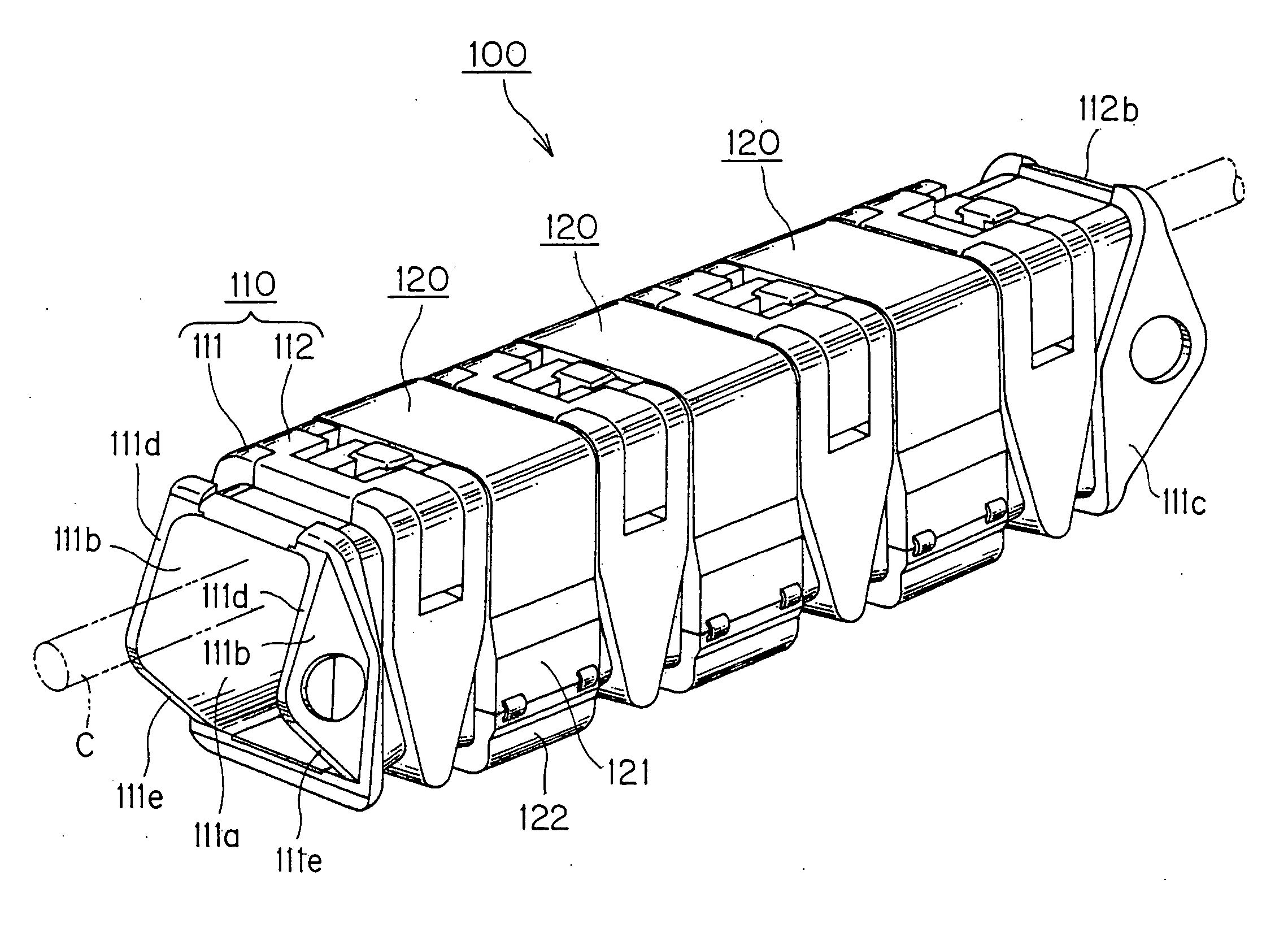
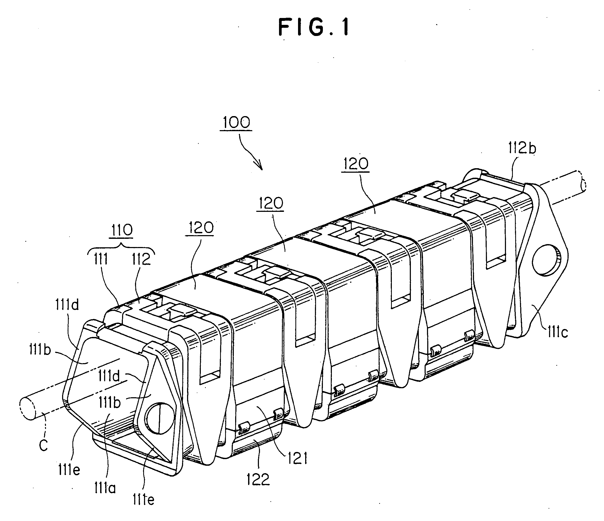
[0033] One Example of a closed cable drag chain preferable as the present invention will be described with reference to FIGS. 1 and 3. FIG. 1 is an assembly finished view of a closed cable drag chain, which is one Example of the present invention, FIG. 2 is an assembly view in which outer frames of the closed cable drag chain shown in FIG. 1 were removed, FIG. 3 is an assembly view in which the outer frames and opening / closing lid members of the closed cable drag chain shown in FIG. 1 were removed, FIG. 4 is a disassembled view of the closed cable drag chain shown in FIG. 1, and FIG. 5 is a side sectional view showing a state of the operation of the closed cable drag chain shown in FIG. 1.

[0034] A closed cable drag chain 100 of the present Example has a basic structure as shown in FIGS. 1 to 4, in which a number of intermediate frames 110 are articulately connected to each other to form a tubular shape and by fit-covering a removable outer frame 12...


PUM

PropertyMeasurementUnit
tensionaaaaaaaaaa
strengthaaaaaaaaaa
wear resistanceaaaaaaaaaa

Abstract

To provide a closed cable drag chain, which is capable of preventing the contact wear powder generated in the holding and guiding the inserted cable or the like from being scattered into an operation space, and of suppressing noises such as sliding contact noise and scattering sounds, and wherein the assembling, maintenance and repair are easy and early wear of the cable or the like can be suppressed. In a closed cable drag chain in which a cable or the like C is inserted into said chain in a tubular fitting state where removable outer frames 120 fit-covers connecting spaces S between a number of adjacent intermediate frames 110 to close the connecting spaces S therebetween respectively, whereby the cable or the like is guided while being held, a connecting portion 111c provided with engraved pin hole on a rear side of the intermediate frame body is integrally two-color injection molded with a polyamide resin softer than a glass-fiber reinforced polyamide resin forming other portions of the intermediate frame body 111.

Description

[0001] This application claims priority to Japanese Patent Application No. 2002-321425 filed Nov. 5, 2002.TECHNICAL FIELD TO WHICH THE INVENTION PERTAINS[0002] The present invention relates to a technical field of a cable drag chain, which holds and guides an electric cable, or a hydraulic or pneumatic hose between a mobile portion, which is operated while moving, and a fixed portion, in a machine tool, a civil engineering machinery, a transfer system or the like.RELATED ART[0003] When a cable or a hydraulic or pneumatic hose is connected to a device, which operates while moving, such as a machine tool, a civil engineering machinery, a transfer system or the like, undue torsion or tension can be generated in the cable or hose due to by its movement thereby damaging a cable or a hose in an exposed state and disordering its outward appearance. Therefore, a cable drag chain for holding and guiding an inserted cable or hose has been proposed.[0004] A conventional cable drag chain 500 ha...

Claims


Application Information

Patent Timeline
Patent Type & Authority Applications(United States)
IPC IPC(8): B29C45/16B29L31/00F16G13/16H02G3/04H02G3/30H02G3/38H02G11/00
CPCH02G11/006F16G13/16
Inventor KOMIYA, SHOICHIRO
Owner TSUBAKIMOTO CHAIN CO
Why Eureka
Try Eureka