Method and system for processing regions of interest for objects comprising biological material

a biological material and object technology, applied in the field of biological material processing, can solve the problems of preventing efficient processing of regions of interest, affecting the efficiency of the techniques available in the field of automated assembly fail to provide a way to efficiently process donor and recipient blocks, etc., to achieve the effect of better comparison

Inactive Publication Date: 2004-05-06
GOVERNMENT OF THE UNITED STATES OF AMERICAS AS REPRESENTED BY THE SEC OF THE DEPT OF HEALTH & HUMAN SERVICES THE +1
View PDF35 Cites 201 Cited by
  • Summary
  • Abstract
  • Description
  • Claims
  • Application Information

AI Technical Summary

Benefits of technology

0068] FIGS. 48A and 48B schematically illustrate how the arrays can provide a comprehensive analysis of a molecular marker in a group of tissue specimens (such as different tumors) at the population level, instead of at the level of an individual tumor specimen.
0069] FIG. 49 is a drawing which schematically illustrates use of the arrays as co

Problems solved by technology

The techniques available in the field of manufacturing, however, fall short when applied to certain applications.
Other limitations of the prior art prevent efficient proc

Method used


Image

  • Method and system for processing regions of interest for objects comprising biological material
  • Method and system for processing regions of interest for objects comprising biological material
  • Method and system for processing regions of interest for objects comprising biological material

Examples


example 2

Physical Object

[0096] FIG. 5 shows a physical object 504 including a set of reference points 512, 514, and 516 on the object. In the example, the reference points can be identified because they are of different colors (e.g., red, green, and blue). However, a variety of other techniques can be used. For example, different shapes or sizes can be used. The advantage of such an arrangement is that the identity of the reference points can be determined if the object is rotated or a mirror image or some other distortion of the physical object is obtained. For convenience, a representation of the reference points stored in a computer-readable medium might indicate an identifier (e.g., "2").

[0097] FIG. 6 shows a physical object 604 including a set of reference points 612, 614, and 616 on the object are placed at locations with respect to the edges to facilitate determining identity of the reference points. In the example, the physical object 604 is rectangular in shape and thus has 4 edges....

example 3

Region of Interest

[0102] Although some examples show a single region of interest for an object, there may be one or more regions of interest on an object. Information indicating the location and extent of a region of interest can be stored in computer-readable media for retrieval at a later time. The regions of interest can take a variety of shapes and sizes. In addition, it may be advantageous to define certain regions inside a region of interest as not being part of the region of interest.

[0103] In some cases, the region of interest may contain a removable resource. In such a scenario it may be advantageous to track removal of the resource to determine how much, if any, of the resource remains for a set of regions, a region, a set of objects, or an object. Such an arrangement can be accomplished by maintaining a database identifying the regions, the objects, and the amount of resource remaining. When a resource is removed, the database can be updated to so reflect.

example 4

Generating Information Indicating a Region of Interest

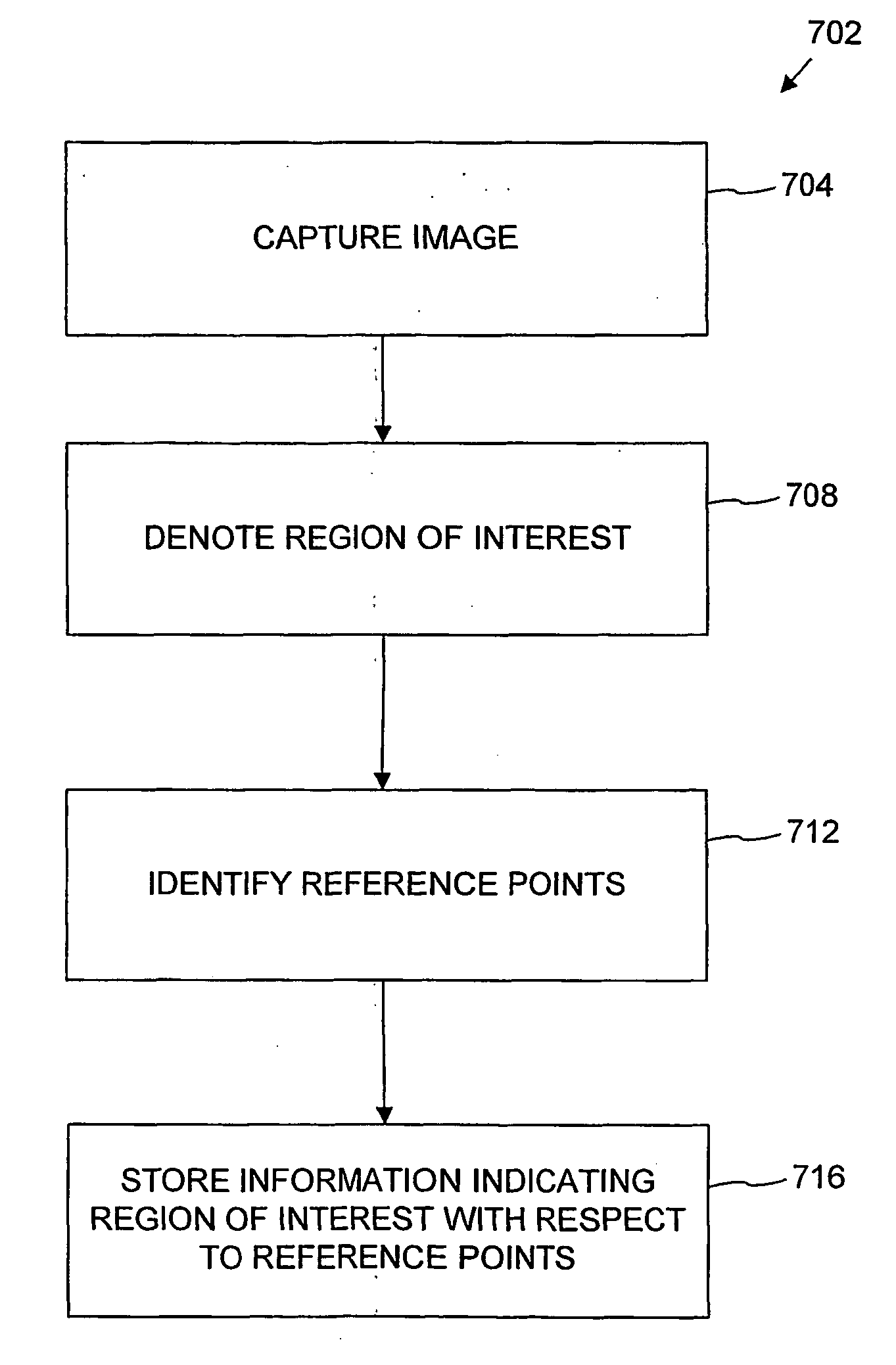
[0104] FIG. 7 shows an exemplary method 702 for generating information indicating the location and extent of a region of interest for a physical object. In the example, the information is indicated with respect to reference points of the object. At 704, an image representative of the physical object is captured. At 708, a region of interest for the physical object is denoted. As described in more detail below, such denotation can be achieved by physically marking the physical object, but physical marking is not required. Also, such denotation can be achieved by tracing a region of interest on an image representing the physical object, whether or not the object has been physically marked. At 712, reference points for the physical object are found. Given the reference points and the denoted region of interest for the image representing the physical object, a computer system can store information indicating the location and extent o...


PUM


Abstract

A method and apparatus are disclosed for processing regions of interest for objects comprising biological material. A region of interest can be denoted for a physical object and information indicating the region of interest can be stored in a computer-readable medium for later retrieval. Subsequently, when the object is retrieved, the information indicating the region of interest can be used to generate information specifying a physical location within the region of interest. An operation can then be performed on the physical location within the region of interest. Reference pints within the object can assist in regeneration of the region of interest, and the reference points can be arranged in such a fashion that processing can take rotation of the object into account. The invention includes various features advantageous for constructing tissue microarrays.

Description

RELATED APPLICATION DATA[0001] This application claims priority from PCT Patent Application No. US00 / 34043, entitled "METHOD AND APPARATUS FOR CONSTRUCTING TISSUE MICROARRAYS," filed Dec. 13, 2000, which claims priority from U.S. Provisional Patent Application No. 60 / 170,461, entitled "HIGH-THROUGHPUT, AUTOMATED TISSUE MICROARRAYS CONSTRUCTION, AND DIGITAL IMAGE ANALYSIS," filed Dec. 13, 1999, and U.S. Provisional Patent Application No. 60 / 171,262, entitled "METHODS OF MAKING AND USING TISSUE MICROARRAYS," filed Dec. 15, 1999, all of which are hereby incorporated herein by reference.[0002] The invention generally relates to the fields of computer software and automated processing of physical objects comprising biological material.[0003] Automated retrieval of objects has become commonplace in the field of manufacturing. For example, in the field of automated assembly, computers can direct robotic equipment to retrieve components and appropriately place them on a printed circuit boar...

Claims


Application Information

Patent Timeline
IPC IPC(8): H04N7/18
CPCG01N1/36G01N2001/282G01N2001/368H04N7/18G06T7/0042G06T2207/30072G06K9/00134G06T7/73G06V20/693
Inventor KALLIONIEMI, OLLI PPOHIDA, THOMAS JKARAREKA, JOHNSALEM, GHADI HAMDI
Owner GOVERNMENT OF THE UNITED STATES OF AMERICAS AS REPRESENTED BY THE SEC OF THE DEPT OF HEALTH & HUMAN SERVICES THE
Why Eureka
Try Eureka