Vehicle air conditioner with main blower and sub-blower

a technology of air conditioner and sub-blower, which is applied in refrigeration components, transportation and packaging, light and heating equipment, etc., can solve the problems of increasing the noise of motor operation, increasing the power consumption of the blower but also the operation noise of the motor, and increasing the air blowing nois

Inactive Publication Date: 2004-05-20
DENSO CORP
View PDF7 Cites 59 Cited by
  • Summary
  • Abstract
  • Description
  • Claims
  • Application Information

AI Technical Summary

Problems solved by technology

Thus, if conditioned air is sent to both of the front air passage and the rear air passage by using a single blower of the front air conditioning unit, the volume of air blown off to the rear seat area becomes extremely small.
In this case, however, not only the power consumption of the blower but also operation noises of a motor increase, and further air blowing noises also increase with an increase of air blowing pressure.
Thus, these measures are impractical.
However, when the size of the rear air duct increases it ...

Method used


Image

  • Vehicle air conditioner with main blower and sub-blower
  • Vehicle air conditioner with main blower and sub-blower
  • Vehicle air conditioner with main blower and sub-blower

Examples


first embodiment

[0034] (First Embodiment)

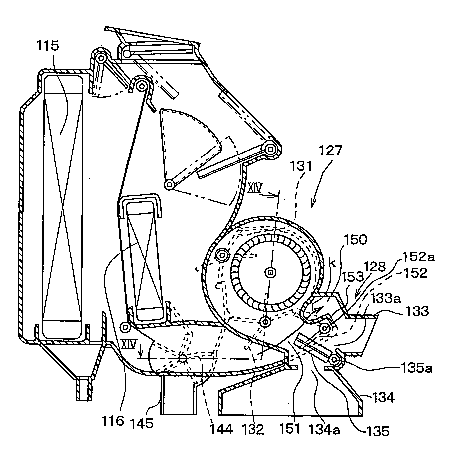
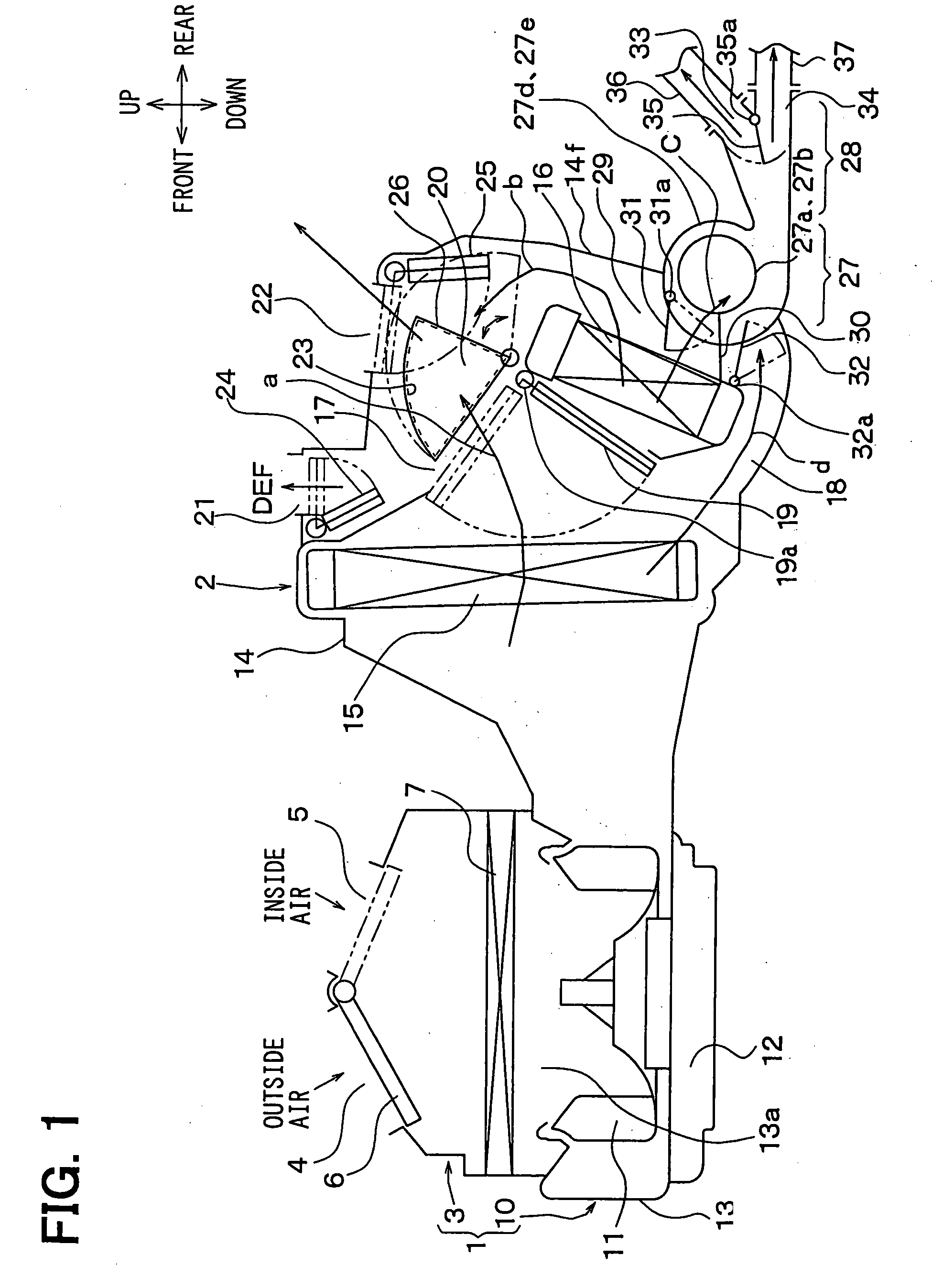
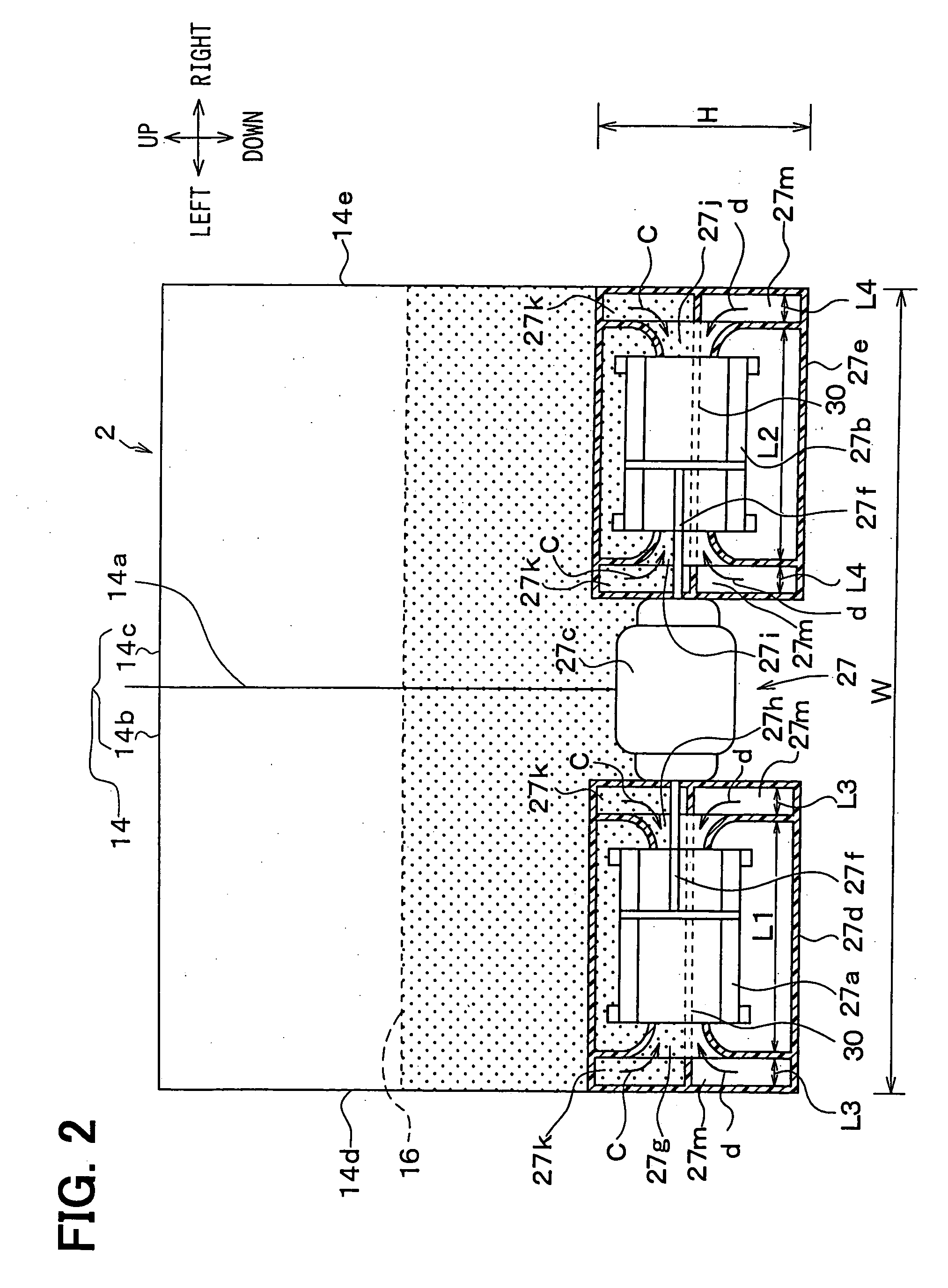
[0035] An interior air conditioning device shown in FIG. 1 is broadly constructed of a blower unit 1 and a heat exchange unit 2. In FIG. 1 and FIG. 2, arrows showing "up and down", "front and rear", and "left and right" indicate directions in a state where the heat exchange unit 2 is mounted in a vehicle, respectively. In FIG. 1, for convenience of preparing a drawing, the blower unit 1 is arranged on the front side of the vehicle of the heat exchange unit 2, but in reality, the blower unit 1 is arranged at an offset position in the lateral direction of the vehicle of the heat exchange unit 2. That is, the heat exchange unit 2 is arranged nearly at the center in the lateral direction of the vehicle inside an instrument panel (i.e., dashboard) in the passenger compartment. The blower unit 1 is arranged to be offset to a front passenger's seat side from the position of the heat exchange unit 2 in the lateral direction of the vehicle.

[0036] The blower unit 1 ha...

second embodiment

[0089] (Second Embodiment)

[0090] The second embodiment of the present invention will be now described with reference to FIG. 3.

[0091] In the above-described first embodiment, the centrifugal fans 27a, 27b in which air flows in the radial direction of a fan impeller are used as the sub-blower 27. However, in the second embodiment, as shown in FIG. 3, a cross flow fan 27n in which air flows through a section normal to the axis of the fan impeller is used as the sub-blower 27.

[0092] In FIG. 3, the same parts as in the first embodiment are denoted by the same reference symbols and their descriptions will be omitted. An air inlet space 40 through which air sent from the blower unit 1 flows is formed in the front portion in the case 14. In the second embodiment, the front temperature adjusting unit and the rear temperature adjusting unit are constructed of well-known film doors 41, 42.

[0093] The front film door 41 is made of a flexible resin film material (resin thin film-shaped member). ...

third embodiment

[0102] (Third Embodiment)

[0103] The third embodiment of the present invention will be now described with reference to FIGS. 4 and 5.

[0104] In the first embodiment, when the rear sub-blower 27 is constructed of blower fans 27a, 27b each made of a centrifugal fan, the driving motor 27 is formed in double shaft type and the blower fans 27a, 27b are arranged on the left and right sides in the axial direction of the driving motor 27c. In the third embodiment, however, when the sub-blower 27 is constructed by the use of the blower fans 27a, 27b each made of a centrifugal fan, as shown in FIGS. 4, 5, the driving motor 27c is provided with another rotary shaft 27f-2 parallel to the rotary shaft 27f-1 of the blower fans 27a, 27b and is arranged on the outer peripheral side of the blower fans 27a, 27b.

[0105] Then, the motor rotary shaft 27f-2 is connected to the fan rotary shaft 27f-1 by using a belt 46 to transmit the rotation of the driving motor 27c to the blower fans 27a, 27b via the belt...


PUM


Abstract

A vehicle air conditioner includes a main blower and a sub-blower for blowing air into a passenger compartment. A heat exchange unit for performing a heat exchange with air blown by the main blower is disposed in a case, and the case is provided with a front air passage and a rear air passage. A rear air duct through which air in the rear air passage is introduced to a rear area in the passenger compartment is connected to the case, so that an air flow resistance in the rear air passage becomes larger as compared with the air flow resistance in the front air passage. Further, the sub-blower is disposed integrally with the case for blowing air in the rear air passage to the rear area in the passenger compartment. Accordingly, it can effectively prevent a shortage of an air conditioning capacity in the rear area of the passenger compartment.

Description

[0001] This application is based on Japanese Patent Applications No. 2002-326868 filed on Nov. 11, 2002 and No. 2002-326870 filed on Nov. 11, 2002, the disclosure of which is incorporated herein by reference.[0002] 1. Field of the Invention[0003] The present invention relates to a vehicle air conditioner having a main blower and a sub-blower, which can perform air-conditioning of a plurality of different areas in a passenger compartment by using a single air conditioning unit.[0004] 2. Related Art[0005] There have been proposed various kinds of vehicle air conditioners each of which performs air-conditioning of a plurality of different areas, specifically, a front seat area and a rear seat area in a passenger compartment by using a single air conditioning unit. For example, in a vehicle air conditioner disclosed in JP-A-11-235914, a front air conditioning unit for air-conditioning a front seat area of the passenger compartment is provided with an additional function for blowing off ...

Claims


Application Information

Patent Timeline
IPC IPC(8): B60H1/00
CPCB60H1/00028B60H2001/002B60H2001/00099
Inventor ITO, KOJIOKUMURA, YOSHIHIKOTOKUNAGA, TAKAHIROMIYAJIMA, NORIYOSHI
Owner DENSO CORP
Why Eureka
Try Eureka