Retardation compensation system and liquid crystal projector

a compensation system and liquid crystal technology, applied in the direction of instruments, color television details, polarising elements, etc., can solve the problems of narrow viewing angle of liquid crystal devices, inability to increase the contrast ratio of projected images, and disadvantages of projection lens systems, which are disadvantageous in terms of making the projector smaller

Active Publication Date: 2004-05-20
FUJIFILM CORP
View PDF4 Cites 11 Cited by
  • Summary
  • Abstract
  • Description
  • Claims
  • Application Information

AI Technical Summary

Problems solved by technology

The liquid crystal device has the disadvantage of narrow viewing angle because of its birefringence.
Then, it is impossible to increase the contrast ratio of the projected image even if the observer tries to change the viewing angle.
Such projection lens system, however, is disadvantageous in terms of making the projector smaller.
Higher intensity of the light source causes excessive heat to the retardation compensator.
Because of such low durability, it is difficult to utilize the organic retardation compensator to the home use liquid crystal projection TV.
The retardation compensator made of sapphire or crystal has great durability for long-term use, but the sapphire and crystal are expensive.
Accordingly, sapphire or crystal retardation compensator is not appropriate for household type liquid crystal projector in terms of manufacture cost, regardless of great durability.
When the liquid crystal projector adopts the retardation compensator for green light, phase retardation of red and blue light may not be compensated appropriately.
With high and low refractive index materials currently available, however, the wavelength dependences U1 and U2 can not be the same.
In that case, large thickness d2 is required to obtain a designed retardation R2, which is disadvantageous in productivity.

Method used


Image

  • Retardation compensation system and liquid crystal projector
  • Retardation compensation system and liquid crystal projector
  • Retardation compensation system and liquid crystal projector

Examples


embodiment 1

[0075] [Embodiment 1]

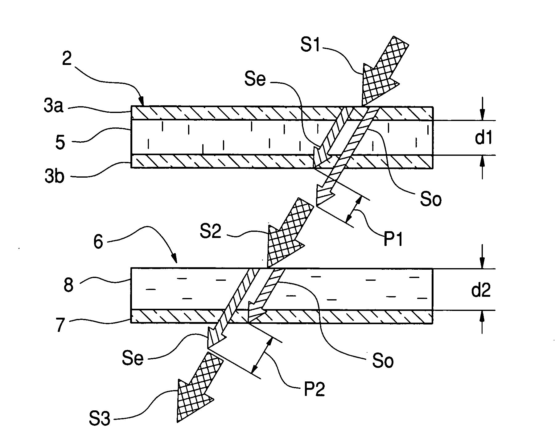
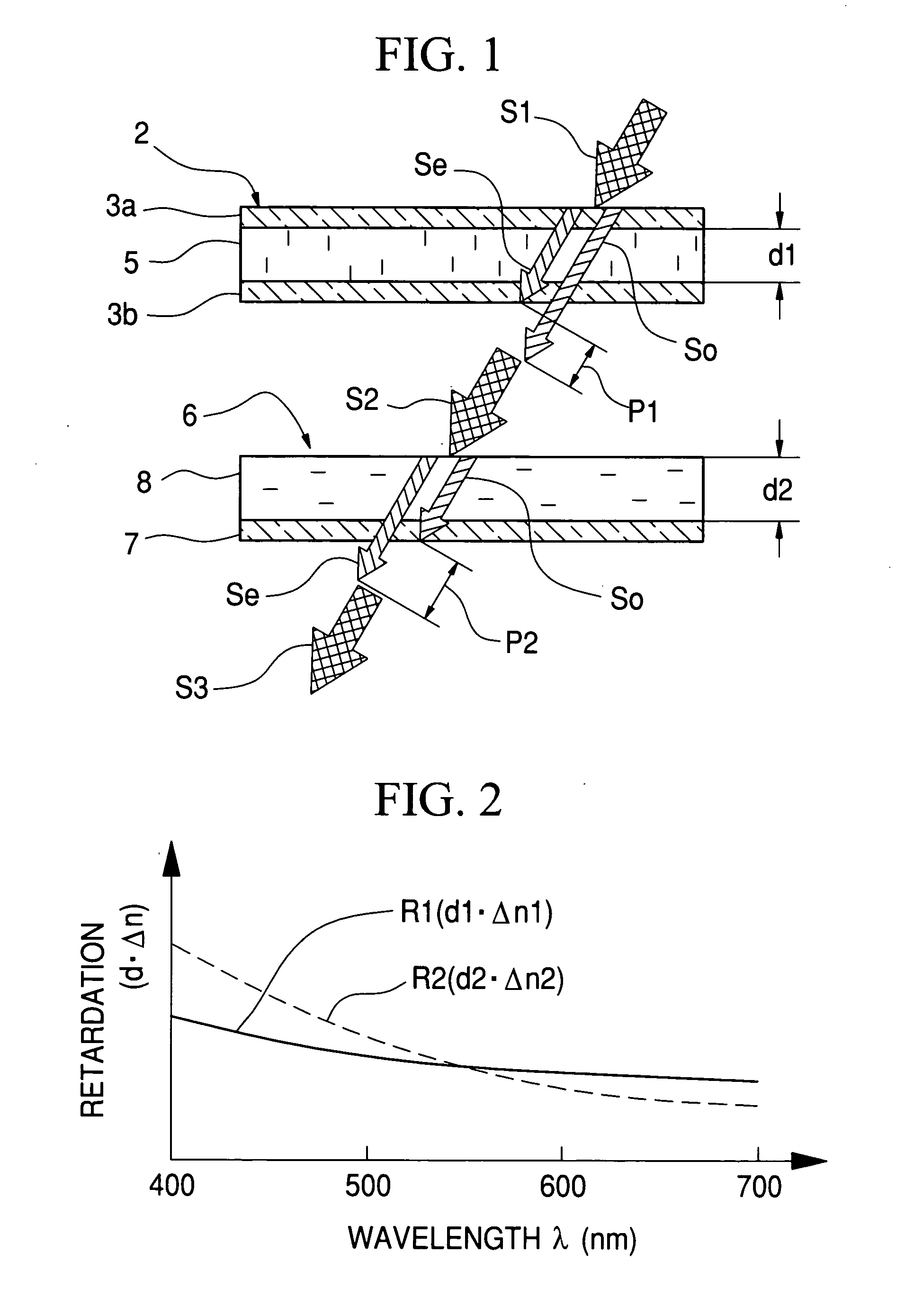
[0076] As shown in FIG. 8, the retardation d.multidot..DELTA.n of nematic liquid crystal material for the TN liquid crystal device has wavelength dependence. Note that the thickness d of the TN liquid crystal device (corresponding to d1 of the liquid crystal layer 5 in FIG. 1) is 4.5 .mu.m. Since all of the liquid crystal molecules in a black state pixel do not orientate perpendicularly, as mentioned above, it is assumed that 70% of the liquid crystal molecules in thickness d cause effective retardation Re to be compensated. The effective retardation Re, calculated by 0.7.times.d.multidot..DELTA.n, is also listed in FIG. 8.

[0077] In this embodiment, the liquid crystal device contains cyanocyclohexanes nematic liquid crystal, known as "ZLI-1083" (Trade Name) manufactured by Merck Ltd. The rate of the liquid crystal molecules to cause the effective retardation is not limited to 70%, but may be decided appropriately in accordance with composition and kind of the li...

embodiment 2

[0091] [Embodiment 2]

[0092] The retardation compensation film (2) according to this embodiment is combined with the ECB liquid crystal device. As shown in the parameters in FIG. 13, the ECB liquid crystal device with the thickness of 4.5 .mu.m has wavelength dependence in the retardation d.multidot..DELTA.n. Since the phase retardation of the ECB liquid crystal device is caused by the wavelength dependence of the retardation d.multidot..DELTA.n, the retardation of the retardation compensation film may be decided.

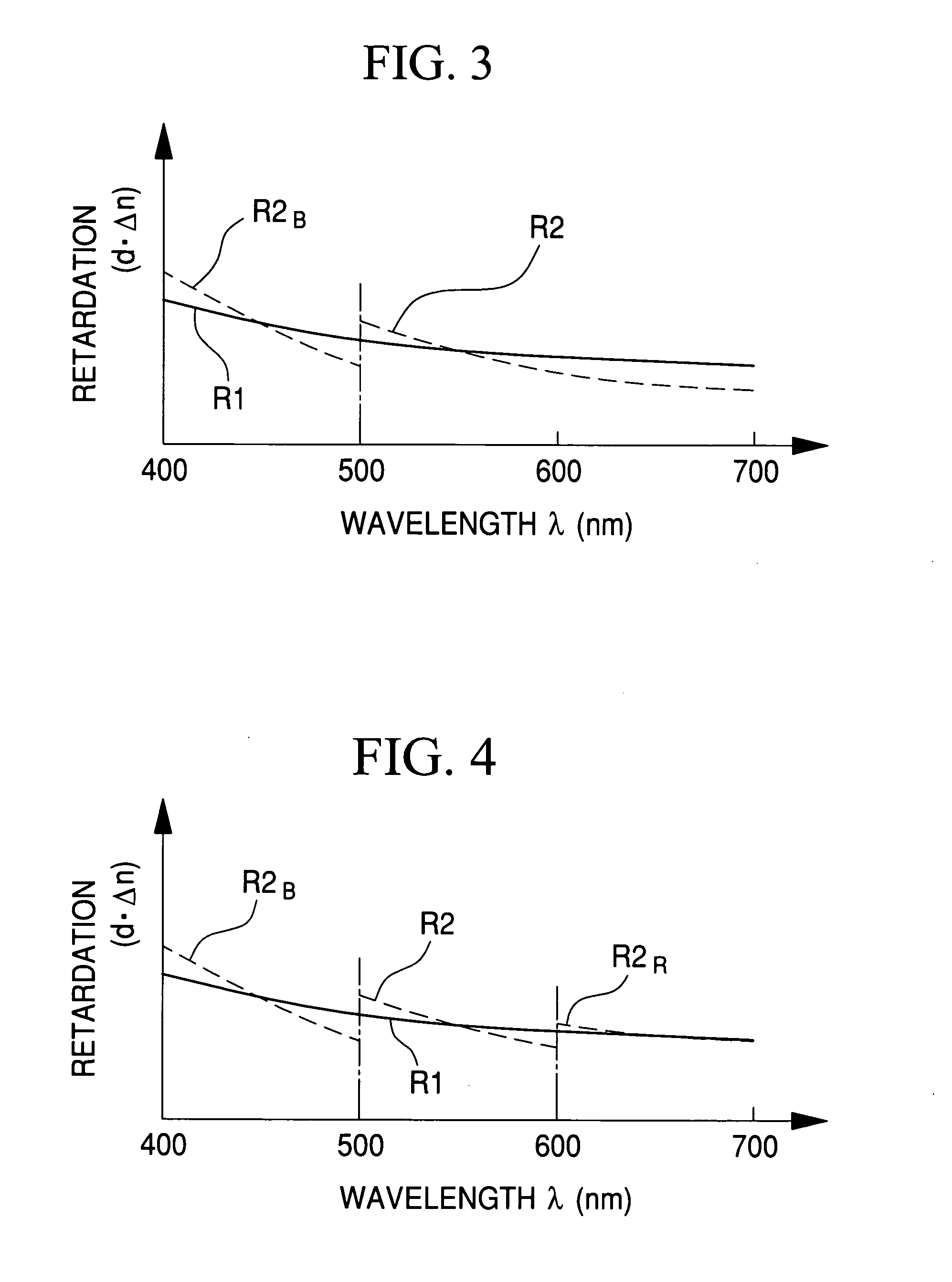
[0093] FIG. 14 shows the parameters of the retardation compensation film (2) for the ECB liquid crystal device. TiO.sub.2 films as the high refractive index layer and SiO.sub.2 films as the low refractive index layer are adapted for the liquid crystal compensation film (2). The thickness of the liquid crystal compensation film is designed so that retardation thereof is the same as the retardation (0.558 nm) of the ECB liquid crystal device at the wavelength of 500 nm. In ord...


PUM

PropertyMeasurementUnit
red wavelengthaaaaaaaaaa

Abstract

Three retardation compensators are provided for compensating the retardation of liquid crystal devices for red, green and blue light, respectively. Each of the retardation compensators is composed of plural high and low refractive index thin film layers alternately layered on a substrate. Because of the difference in the wavelength dependences of the liquid crystal device and the retardation compensator, the retardation R2 of the retardation compensator becomes much larger than the retardation R1 of the liquid crystal device in short wavelength region of the visible band. In order to match the retardation, the thickness of the retardation compensator for blue light is smaller than those for red and green light.

Description

[0001] 1. Field of the Invention[0002] The present invention relates to a retardation compensation system that is effectively applied to a liquid crystal projector having three liquid crystal devices for full color display, and a liquid crystal projector having the retardation compensation system.[0003] 2. Description Related to the Prior Art[0004] A three-panel type liquid crystal projector has three liquid crystal devices for red, green and blue images. The liquid crystal devices modulate red, green and blue light in accordance with three color images to form red, green and blue image lights. The red, green and blue image lights are combined in a combination prism, and focused on the screen through a projection lens system, so that many people can view a full color image at the same time. The above operation of the liquid crystal projector is the same, although the optical system is different in accordance with whether the liquid crystal projector is a front projection type or a r...

Claims


Application Information

Patent Timeline
Patent Type & Authority Applications(United States)
IPC IPC(8): G02F1/13G02B5/30G02F1/13363G03B21/00
CPCG02F1/13363H04N9/3105G02F2001/133637G02F1/133637
Inventor NAKAGAWA, KENICHI
Owner FUJIFILM CORP
Why Eureka
Try Eureka