Solder past printing apparatus and printing method

a printing apparatus and printing method technology, applied in the direction of printing apparatus, manufacturing tools, conductive pattern formation, etc., can solve the problems of insufficient filling time, disadvantageous generation of unfilled portion 9, and defective printing, so as to achieve further reduction of printing time

Inactive Publication Date: 2004-06-10
PANASONIC CORP
View PDF14 Cites 33 Cited by
  • Summary
  • Abstract
  • Description
  • Claims
  • Application Information

AI Technical Summary

Benefits of technology

[0032] According to a ninth aspect of the present invention, there is provided a solder paste printing apparatus as defined in any one of the first through fifth aspects, wherein a cross-section shape perpendicular to the axial direction of the pressurizing member is varied in the axial direction of the pressurizing member according to a number and a size of the openings of the printing mask, thus varying the pressure to be applied from the pressurizing member to the solder paste against the printing mask.
[0042] According to a 14th aspect of the present invention, there is provided a solder paste printing method as defined in the 11th aspect, wherein a cross-section shape perpendicular to the axial direction of the pressurizing member is varied in the axial direction of the pressurizing member according to a number and a size of the openings of the printing mask, thus varying the pressure to be applied from the pressurizing member to the solder paste against the printing mask.
[0230] Moreover, it is preferred that a pressurizing member 28C has a built-in heat-generating element 38 as shown in FIG. 8 and appropriately heats the solder paste 7 up to a temperature of about 20 to 30.degree. C. The pressurizing member 28C having the built-in heat-generating element 38 appropriately heats the solder paste 7 and maintains the temperature of the solder paste 7 constant, by which the viscosity of the solder paste 7 is maintained constant, allowing a stable filling characteristic to be obtained.
[0239] Moreover, the first embodiment has the construction in which the squeegees 12a and 12b are vertically moved. However, as in FIG. 10 showing the solder paste printing apparatus of the second embodiment of the present invention, both the squeegees may consistently brought in contact with the surface 3a of the printing mask 3 without the vertical (up-and-down) movement during printing. The printing apparatus shown in FIG. 10 executes the filling and scraping operations of the solder paste 7 in the state in which a pair of squeegees 12a, 12b are consistently brought in contact with the printing mask 3 during printing, releases the application pressure that has been applied when the movement of the squeegees 12a and 12b is ended, and then separates the printed board 5 from the printing mask 3. By repeating this operation, the printing is continuously performed. By this operation, the solder paste 7 is consistently held between both the squeegees 12a and 12b, and the up-and-down movement of the squeegees 12a and 12b can be eliminated, allowing the printing time to be further reduced. When the printing ends, both the squeegees 12a and 12b are moved up by the drive devices 16 and 18 and held in the standby position 20. Since the printing apparatus shown in FIG. 10 has the same construction as that of the printing apparatus shown in FIG. 1 although the operation control is varied, no description is provided for the construction.
[0240] It is to be noted that the reference numeral 50 denotes a side plate provided so as to stride over either one or both of the squeegees 12a and 12b and is able to prevent the solder paste 7 from moving into a position displaced from the squeegees 12a and 12b in the axial direction of the squeegees 12a and 12b.

Problems solved by technology

However, if the travel speed (squeegee speed) of the squeegee 101a is increased in the conventional solder paste printing apparatus 100 for the reduction of the above-mentioned time, the so-called unfilled portion 9, where the amount of the solder paste 7 filled into the openings 4 of the printing mask 3 becomes insufficient, is generated as shown in FIG. 17, causing defective printing.
Therefore, a sufficient filling time cannot be obtained.
As a result, the unfilled portion 9 is disadvantageously generated.
As described above, the conventional solder paste printing apparatus has not been able to achieve both of an increase in the printing speed and stable printing.

Method used


Image

  • Solder past printing apparatus and printing method
  • Solder past printing apparatus and printing method
  • Solder past printing apparatus and printing method

Examples


working example 2

[0249] In the working example 2, the printing conditions depending on a change in the cross-section shape of the pressurizing member was observed. Other printing conditions are roughly similar to those of the working example 1.

[0250] Sample e: a circular cross-section having a diameter d of 5 mm.

[0251] Sample f: a semicircular cross-section having a diameter d of 5 mm, and the angle .theta. with respect to the printing mask is set to 30 degrees (FIG. 6).

[0252] Sample g: a semicircular cross-section having a diameter d of 8 mm, and the angle .theta. with respect to the printing mask is set to 30 degrees (FIG. 6).

[0253] Sample h: a semicircle having a diameter d of 8 mm is processed into a wedge-shaped cross-section with an angle .beta. set to 30 degrees leaving the diametrical surface, and the angle .theta. with respect to the printing mask is set to 30 degrees (FIG. 7).

[0254] Sample i: a circular cross-section having a diameter d of 6 mm.

[0255] Sample j: a circular cross-section hav...

second embodiment

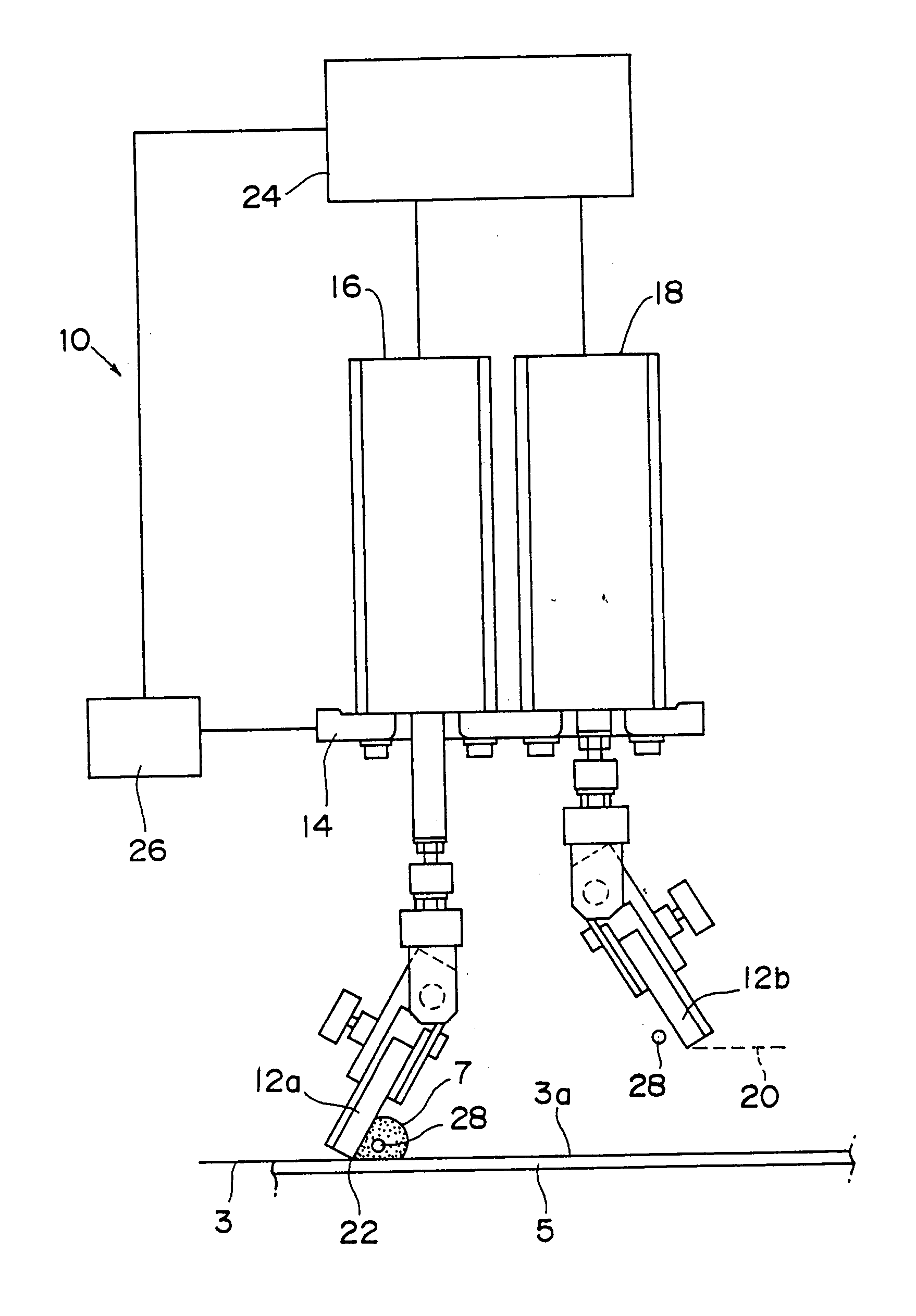
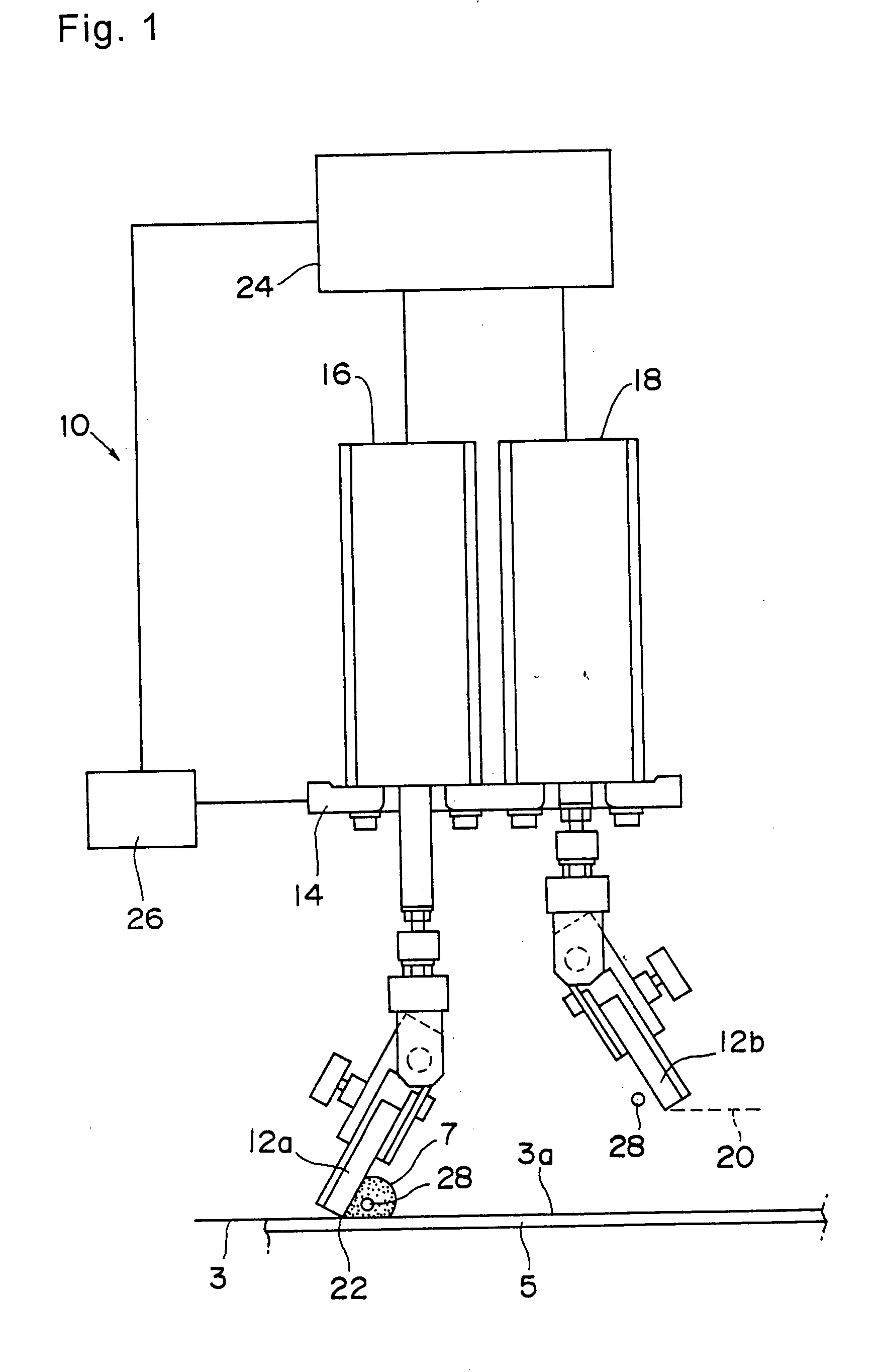
[0264] Moreover, particularly in the second embodiment, a pair of squeegees 12a and 12b is provided, and both the squeegees 12a and 12b are consistently brought in contact with the printing mask 3 at least during printing. Therefore, the take-out of the solder paste 7 by the rising squeegees 12a and 12b is prevented, and the set amount of solder paste 7 can be consistently held on the printing mask 3. Moreover, neither the squeegee 12a nor 12b vertically moves during printing. Therefore, the printing time can be reduced, and the productivity can be improved.

[0265] Moreover, as shown in FIG. 26A, if the printing is repetitively performed with the conventional construction, the solder paste 7 is protruded from both sides of the squeegee 12a. The solder paste 7A protruded therefrom does not naturally return, and the operator collects and puts back the paste at regular intervals of time or dispose of it. In contrast to this, by applying a pressure to the solder paste 7 with the pressuri...

third embodiment

[0271] (Third Embodiment)

[0272] In the solder paste printing apparatus of the third embodiment of the present invention, as shown in FIG. 20 through FIG. 23, the pressurizing member 28 of a round bar is rotated in the direction opposite to the rolling direction of the solder paste 7.

[0273] The pressurizing member 28 of a round bar is rotatably supported by a pair of brackets 30 and 30, one end of the pressurizing member 28 is made to project from one bracket 30, and a pulley 53 is fixed to the projecting end. A motor 49 is arranged in the vicinity of the pressurizing member 28 of the one bracket 30, and a pulley 52 fixed to a rotary shaft of motor 49 and the pulley 53 located at the projecting end portion of the pressurizing member 28 are connected to each other by means of a belt 54. With this arrangement, if the rotary shaft of the motor 49 is rotated counterclockwise in FIG. 20, then the pressurizing member 28 is to be rotated counterclockwise (in a direction of the arrow Y in FI...


PUM

PropertyMeasurementUnit
travel speedaaaaaaaaaa
heightaaaaaaaaaa

Abstract

When solder paste passes through a first gap (34) located between a pressurizing member (28) and a printing mask (3) during solder paste printing, a pressure directed toward the printing mask is applied from the pressurizing member to the solder paste.

Description

[0001] The present invention relates to a solder paste printing apparatus and printing method for printing a solder paste on a surface of a circuit-forming body, for example, a circuit board, which is an object to be printed.[0002] Conventionally, a solder paste has mainly been used when soldering an electronic component such as a chip component on a printed board in manufacturing an electronic circuit board, and a solder paste printing apparatus is used for printing this solder paste in the desired pattern. As one example of the squeegee head mounted on a conventional solder paste printing apparatus, a construction as shown in FIG. 13 can be enumerated.[0003] Normally, during a printing operation, a squeegee head 102 reciprocates from the left to the right and from the right to the left in FIG. 13 every printed board 5. In this case, a rightward direction printing squeegee 101a is used for the rightward direction printing from the left to the right, and a leftward direction printin...

Claims


Application Information

Patent Timeline
Patent Type & Authority Applications(United States)
IPC IPC(8): B41F15/46H05K1/02H05K3/00H05K3/12H05K3/26
CPCB41F15/46H05K1/0269H05K3/0008H05K3/1216H05K3/1233H05K2203/167H05K2201/09918H05K2203/0139H05K2203/0278H05K2203/082H05K2203/163H05K3/26
Inventor ONISHI, HIROAKIMIMURA, TOSHINORICHIKAHISA, NAOICHITAKAHASHI, KENMURAKAMI, TOSHIYUKINAKAHIRA, HITOSHINAGASHIMA, SADAYUKI
Owner PANASONIC CORP
Why Eureka
Try Eureka