Cervical canal dilator

a cervical canal and dilator technology, applied in the field of cervical dilation devices, can solve the problems of over-expansion and damage to the cervix, limited gutnick structure of the elastic dilating member and the inflation process thereof, and limited ability to accurately produce a specific or controlled maximum inflation diameter

Inactive Publication Date: 2004-06-17
OS TECH
View PDF5 Cites 67 Cited by
  • Summary
  • Abstract
  • Description
  • Claims
  • Application Information

AI Technical Summary

Problems solved by technology

Gutnick, however, is limited by the combination of the structural material of the dilating member being elastic and the inflation process of supplying a controlled volume of liquid to the elastic dilating member to produce an inflated diameter of the elastic member which is stated in one example as "about somewhat greater than 10 mm and preferably expand up to about 15 mm."
Thus, the structure of the Gutnick elastic dilating member and the inflation process thereof is limited in its ability to accurately produce a specific or controlled desirable maximum inflation diameter.
The Gutnick method to determine the diameter of inflation relative to a given volume is not directly measured and thus is highly subjective, vulnerable to varying lengths of conduits and fluid losses and is therefore also vulnerable to being overly expanded and damaging the cervix.
This can result in a partial or an uneven dilation of the cervix because the combination of the length of the second inflatable member relative to its placement in the cervix can be too short to adequately treat all cervixes.
Finally, the disc member limits the visualization of the positioning of the dilator into the cervical canal adding further risk of harm to the patient.
Levine is limited by its inability to

Method used


Image

  • Cervical canal dilator
  • Cervical canal dilator
  • Cervical canal dilator

Examples


Embodiment Construction

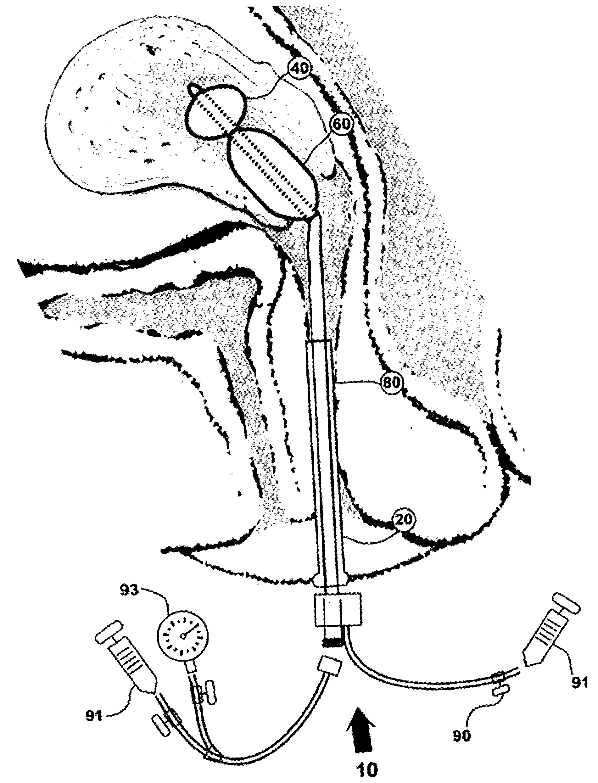
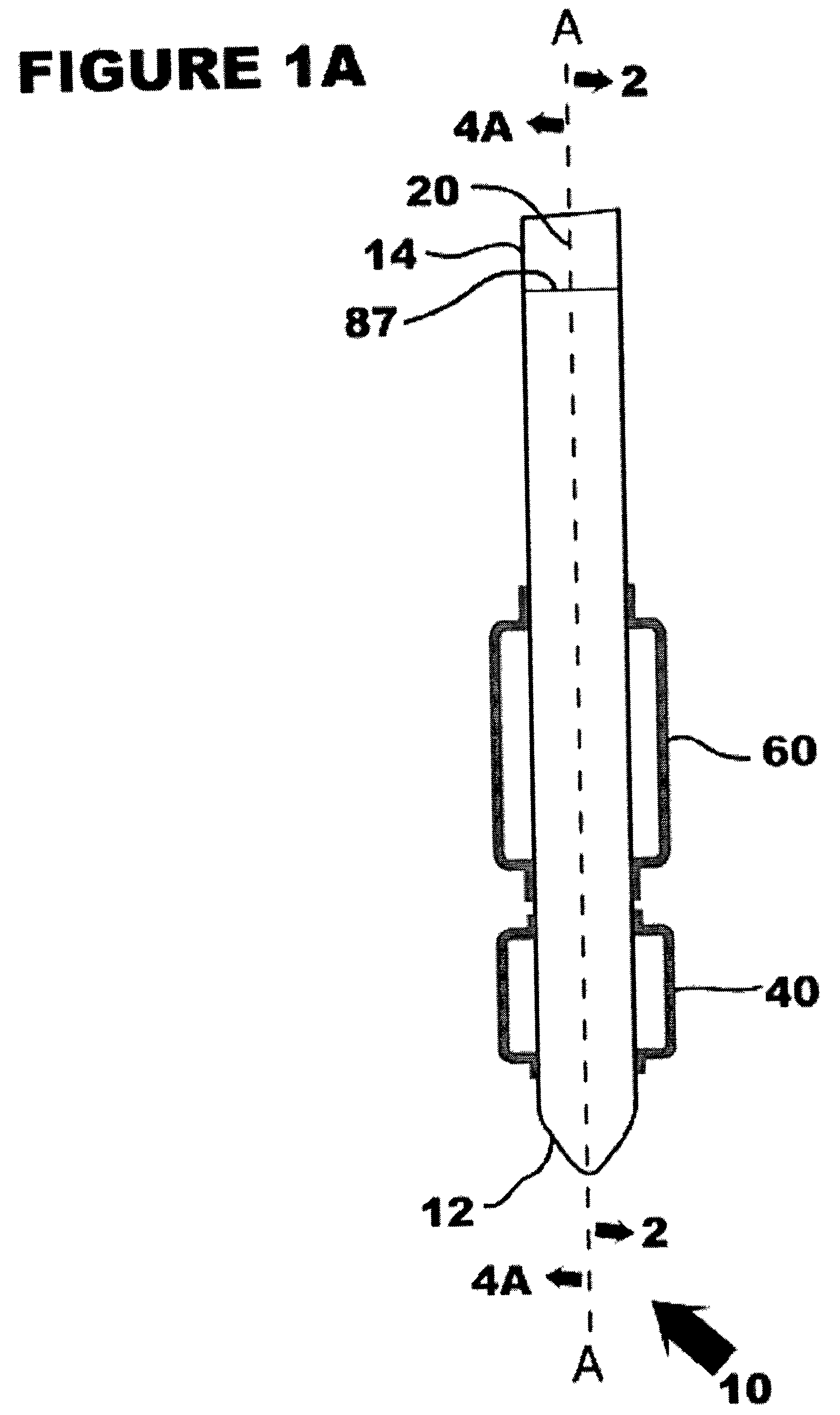
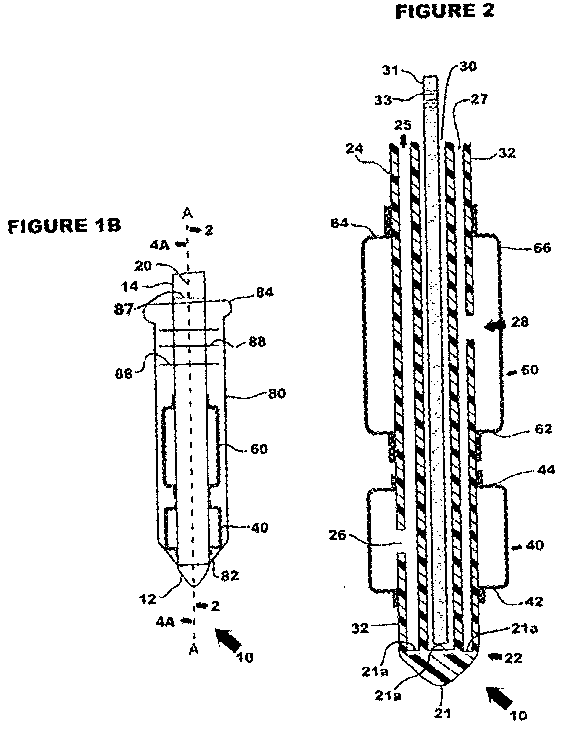
[0033] Referring now in specific detail to the drawings in which like referenced numerals identify similar or identical elements throughout the several views, and initially to FIG. 1A, a novel cervical canal dilator assembly 10 is shown having a shaft 20, a first inflatable member 40, a second inflatable member 60 and a control system 90 (see FIG. 3). Cervical canal dilator assembly 10, hereinafter referred to as "dilator 10" has a distal end 12 and a proximal end 14 defining a longitudinal axis-A.

[0034] In FIG. 1B, the novel cervical canal dilator assembly 10 is shown having a sheath 80. Sheath 80 includes markings 88 for correlating the position of the first inflatable member relative to the proximal end of the sheath. Shaft 20 includes markings 87 for correlating the position of sheath 80 relative to the inflatable members. Dilator 10 is adapted for use by a physician and is configured as a readily useable disposable device having a reduced cross-sectional dimension of less than ...


PUM


Abstract

A cervical canal dilating assembly and method of use are shown. The dilator assembly includes a plastic shaft, a first inflatable member, and a second inflatable member. The shaft can range from being rigid to being highly flexible. The second inflatable member is fabricated of a non-elastic material and is configured to have a maximum inflatable diameter. The second inflatable member is configured to have a predetermined maximum inflatable diameter ranging from 4 to 20 mm. The dilating assembly can also be at least partially covered by a sheath. A control system includes means for measuring pressure configured for at least monitoring the pressure of the second inflatable member. A wire can be used in selected configurations to stiffen and shape the shaft. In operation, the initial penetration of the dilating assembly into the uterus uses a wire for increased stiffness. The dilating assembly is then forwarded through the remainder of the cervical canal. The first inflatable member is expanded in the uterus after being uncovered by the sheath. The second inflatable member is positioned in the cervical canal and gradually inflated to a predetermined maximum diameter.

Description

[0001] 1. Technical Field[0002] The present disclosure relates to devices for cervical dilation. More particularly, the present disclosure relates to devices for cervical dilation using inflatable members.[0003] 2. Background of Related Art[0004] Cervical canal dilators having tubular shafts with inflatable expanding members, such as balloons, are well known and have functions ranging from incontinence catheters to assisting in childbirth. One or more balloons are inflated after positioning the dilator through the cervical canal. The expanded balloons secure the tubular shaft in position and, in combination with the function of dilation, frequently provide the critical passageway for fluid passage, diagnostic devices, or treatment instruments.[0005] A device and process for cervical dilation prior to an abortion is described in U.S. Pat. No. 3,848,602 to Gutnick. The device includes an elongate shaft member formed of firm flexible material and terminating in a distal end with a roun...

Claims


Application Information

Patent Timeline
IPC IPC(8): A61BA61F2/958A61M29/00A61M29/02A61M31/00
CPCA61M25/1011A61M25/1018A61M2025/0063A61M31/00A61M29/02A61M25/10181A61M25/10184A61M25/10187A61M25/10182
Inventor FOLTZ, JONATHANREED, DAVIDOLIVE, DAVID
Owner OS TECH
Why Eureka
Try Eureka