Refrigerant cycle system
a refrigerant cycle and cycle system technology, applied in refrigeration components, subcoolers, lighting and heating apparatus, etc., can solve the problems of reducing the cooling performance of the flow amount of refrigerant circulated in the refrigerant cycle cannot be adjusted, and the flow amount of refrigerant circulated in the refrigerant cycle system is extremely low
- Summary
- Abstract
- Description
- Claims
- Application Information
AI Technical Summary
Benefits of technology
Problems solved by technology
Method used
Image
Examples
first embodiment
[0041] (First Embodiment)
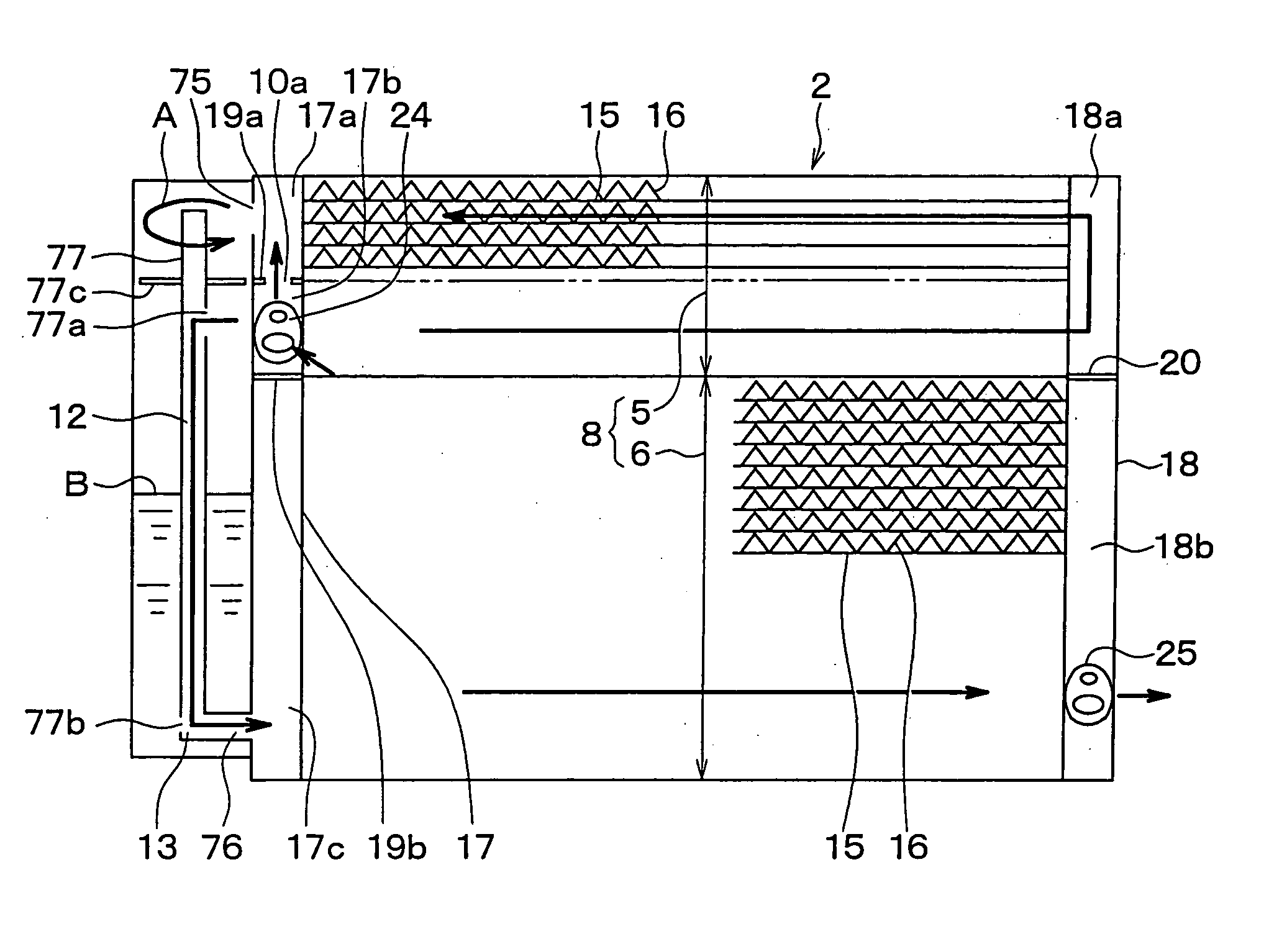
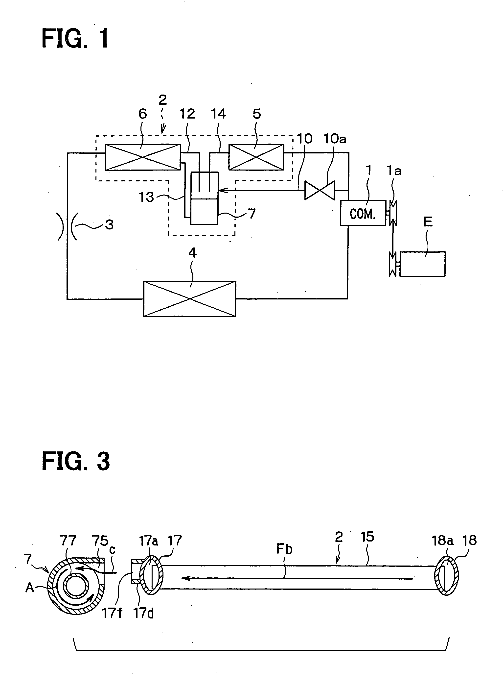
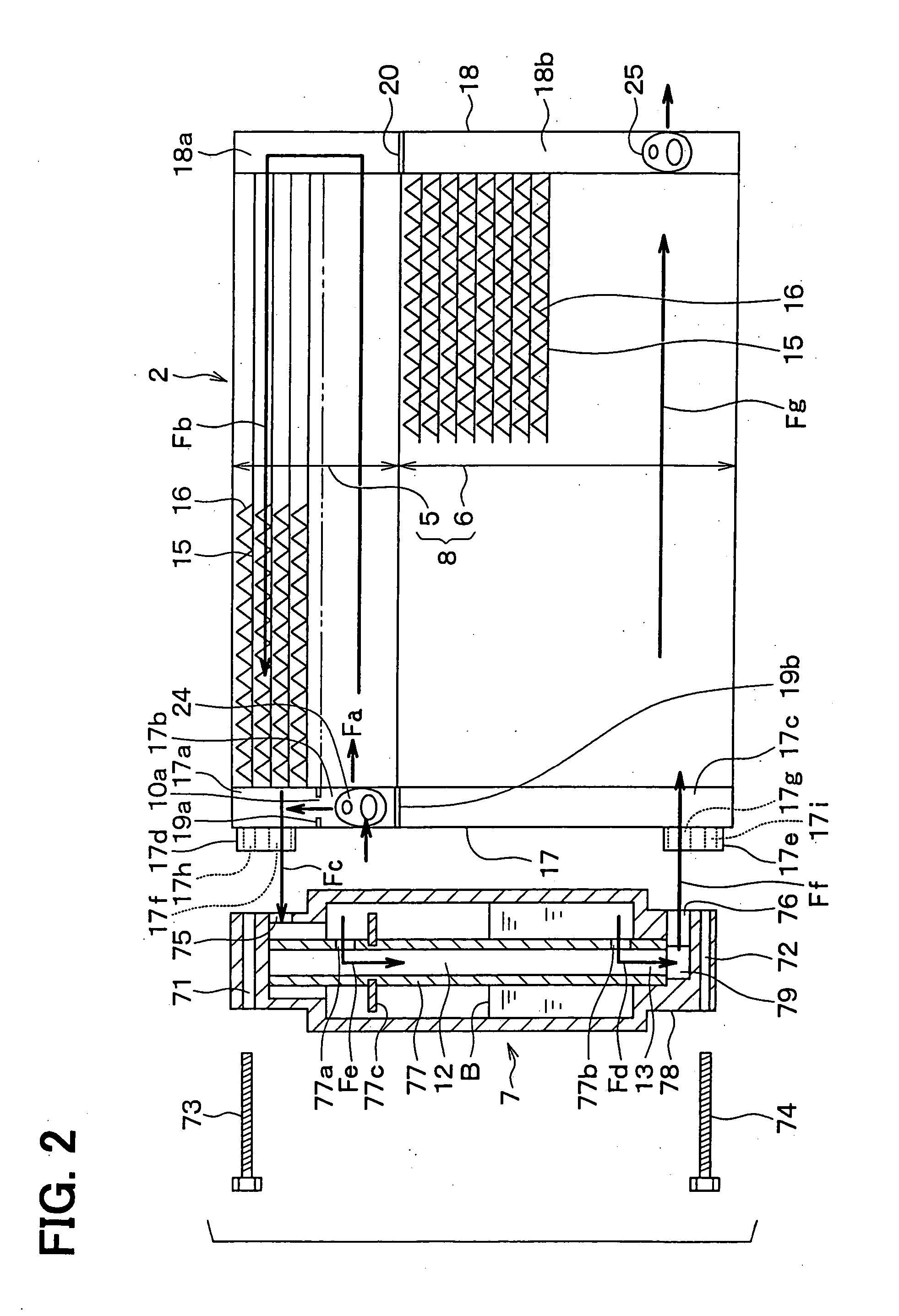
[0042] The first embodiment of the present invention will be now described with reference to FIGS. 1-3. In the first embodiment, a refrigerant cycle system shown in FIG. 1 is typically used for a vehicle air conditioner. In FIG. 1, a compressor 1 is driven by a vehicle engine E through a solenoid clutch 1a and a belt hung thereon. High-pressure and high-temperature refrigerant is discharged from the compressor 1, and is circulated into a separator-integrated condenser 2. In the condenser 2, the refrigerant is heat-exchanged with and cooled by outside air, and is condensed. The condenser 2 is disposed at a portion to be cooled by receiving running wind in a vehicle running. Specifically, the condenser 2 is disposed at a front area in an engine compartment, and is cooled by the running wind and air blown by a cooling fan (not shown).
[0043] A decompression device 3 decompresses refrigerant after passing through the condenser 2 to a low-pressure and gas-liquid r...
second embodiment
[0065] (Second Embodiment)
[0066] In the above-described first embodiment, the gas-liquid separator 7 is fixed by using the bolts 73, 74 to the left header tank 17 of the condenser 2. However, in the second embodiment, as shown in FIG. 4, the gas-liquid separator 7 is integrally brazed to the left header tank 17 of the condenser 2. Specifically, the gas-liquid separator 7 has a flat outer-wall surface on a side having the refrigerant inlet 75. That is, the gas-liquid separator 7 has a flat outer-wall surface that is bonded to the left header tank 17 by the brazing. The gas-liquid separator 7 is integrally brazed to the left header tank 17 while its flat outer-wall surface contacts an outer wall surface of the left header tank 17. Therefore, in the second embodiment, the components such as the connection joints 17d, 17e and the bolts 73, 74 in the first embodiment can be eliminated, thereby simplifying the construction, and eliminating screwing work of the bolts 73, 74. In the second ...
third embodiment
[0067] (Third Embodiment)
[0068] In the above-described first and second embodiments, the liquid-refrigerant return passage 13 into which a part of liquid refrigerant stored in the gas-liquid separator 7 flows, is connected to the inlet side of the second heat-exchanging portion 6. However, in the third embodiment, as shown in FIG. 5, the liquid-refrigerant return passage 13 is connected to the outlet side of the second heat-exchanging portion 6. Further, as in the second embodiment, the gas-liquid separator 7 is integrally brazed to the left header tank 17.
[0069] In the third embodiment, as shown in FIG. 6A, three partition plates 19a, 19b, 19c are arranged in the up-down direction in the left header tank 17 of the condenser 2, thereby partitioning the inner space of the left header tank 17 into four spaces 17a, 17b, 17c', 17c" in the up-down direction. The partition plates 19a, 19b, the upper space 17a and the intermediate space 17b in the third embodiment correspond to those in th...
PUM
 Abstract
Description
Claims
Application Information
 - R&D
- Intellectual Property
- Life Sciences
- Materials
- Tech Scout
- Unparalleled Data Quality
- Higher Quality Content
- 60% Fewer Hallucinations
Browse by: Latest US Patents, China's latest patents, Technical Efficacy Thesaurus, Application Domain, Technology Topic, Popular Technical Reports.
© 2025 PatSnap. All rights reserved.Legal|Privacy policy|Modern Slavery Act Transparency Statement|Sitemap|About US| Contact US: help@patsnap.com


