Refrigerant cycle system

a cycle system and refrigerant technology, applied in refrigeration components, subcoolers, lighting and heating apparatus, etc., can solve the problems of reducing the flow amount of refrigerant circulated in the refrigerant cycle cannot be adjusted, and the cooling performance of the refrigerant cycle system is reduced. , to achieve the effect of reducing the production cost of the condenser, reducing the refrigerant passage structure of th

Inactive Publication Date: 2006-01-03
DENSO CORP
View PDF5 Cites 14 Cited by
  • Summary
  • Abstract
  • Description
  • Claims
  • Application Information

AI Technical Summary

Benefits of technology

[0012]It is another object of the present invention to simplify a refrigerant passage structure of a condenser in the refrigerant cycle system.
[0013]According to an aspect of the present invention, a refrigerant cycle system includes a first heat-exchanging portion for cooling and condensing gas refrigerant discharged from a compressor by radiating heat, a gas-liquid separator into which all of refrigerant after passing through the first heat-exchanging portion and a part of gas refrigerant discharged from the compressor are introduced, a second heat-exchanging portion disposed downstream of the first heat-exchanging portion for cooling and condensing refrigerant flowing from the gas-liquid separator by radiating heat, a gas-refrigerant return passage through which at least gas refrigerant in the gas-liquid separator is introduced into the second heat-exchanging portion, a decompression device disposed downstream of the second heat-exchanging portion for decompressing refrigerant after passing through the second heat-exchanging portion, and an evaporator disposed downstream of the decompression device for evaporating refrigerant flowing out of the decompression device. Since all of condensed refrigerant (liquid refrigerant) after passing through the first heat-exchanging portion is introduced into the gas-liquid separator, an amount of liquid refrigerant introduced into the gas-liquid separator can be increased. Therefore, an amount of gas refrigerant introduced into the gas-liquid separator can be also increased. As a result, a passage diameter of a gas-refrigerant bypass passage for regulating the gas-refrigerant introduction amount flowing into the gas-liquid separator can be effectively increased. Accordingly, even the passage diameter varies in manufacturing of the condenser, the variation ratio of the gas refrigerant amount introduced into the gas-liquid separator to the liquid refrigerant amount introduced thereinto, due to the passage diameter variation, can be effectively reduced. As a result, the adjusting operation of the liquid refrigerant amount in the gas-liquid separator is not greatly affected by the dimension variations of the gas-refrigerant bypass passage in the manufacturing. Therefore, even if dimension variations are generated in some degree, a refrigerant amount circulated in the refrigerant cycle system can be suitably adjusted in accordance with the super-heating degree of the gas refrigerant discharged from the compressor. In this case, the condenser and the gas-liquid separator are not required to be finely produced, thereby reducing production cost.
[0017]For example, when the inlet portion is disposed outside the first heat-exchanging portion, a gas-refrigerant condensing passage through which the gas refrigerant discharged from the compressor is introduced from the inlet portion into the first heat-exchanging portion is disposed outside the first heat-exchanging portion, and a gas-refrigerant bypass passage through which the gas refrigerant discharged from the compressor is directly introduced into the gas-liquid separator while bypassing the first heat-exchanging portion, is also disposed outside the first heat-exchanging portion. Accordingly, a gas-refrigerant distribution passage (the inlet portion, the gas-refrigerant condensing passage and the gas-refrigerant bypass passage) is not required to be arranged in the first heat-exchanging portion, thereby simplifying the refrigerant passage structure of the condenser, and reducing the production cost of the condenser.
[0018]According to an another aspect of the present invention, a refrigerant cycle system includes a first heat-exchanging portion for cooling and condensing gas refrigerant discharged from the compressor by radiating heat, a gas-liquid separator into which all of refrigerant after passing through the first heat-exchanging portion is introduced, a second heat-exchanging portion disposed downstream of the first heat-exchanging portion for cooling and condensing refrigerant flowing from the gas-liquid separator by radiating heat, and a heating unit for adjusting a heating amount of the liquid refrigerant in the gas-liquid separator in accordance with any one of a super-heating degree of gas refrigerant discharged from the compressor and a super-heating degree of gas refrigerant at an outlet of the evaporator. Because all of the condensed refrigerant from the first heat-exchanging portion is introduced into the gas-liquid separator, the heating amount of the liquid refrigerant in the gas-liquid separator can be set relatively large. Therefore, the heating of the liquid refrigerant in the gas-liquid separator can be readily accurately performed.

Problems solved by technology

As a result, the flow amount of refrigerant circulated in the refrigerant cycle cannot be adjusted in accordance with the super-heating degree of the discharged gas refrigerant.
As a result, the flow amount of refrigerant circulated in the refrigerant cycle system extremely reduces relative to the super-heating degree of the discharged gas refrigerant, thereby reducing cooling performance of the refrigerant cycle system.

Method used


Image

  • Refrigerant cycle system
  • Refrigerant cycle system
  • Refrigerant cycle system

Examples


first embodiment

[0041](First Embodiment)

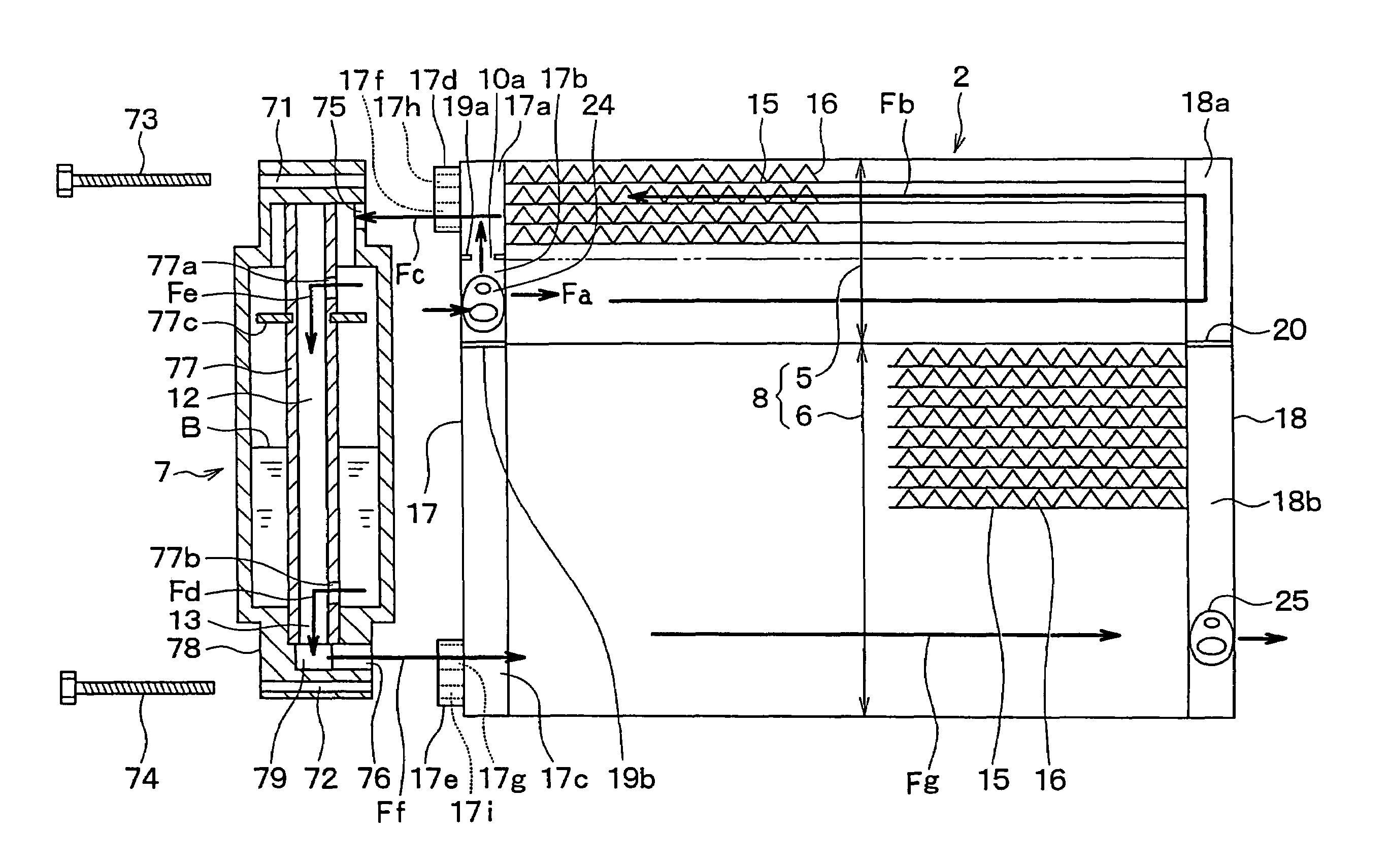
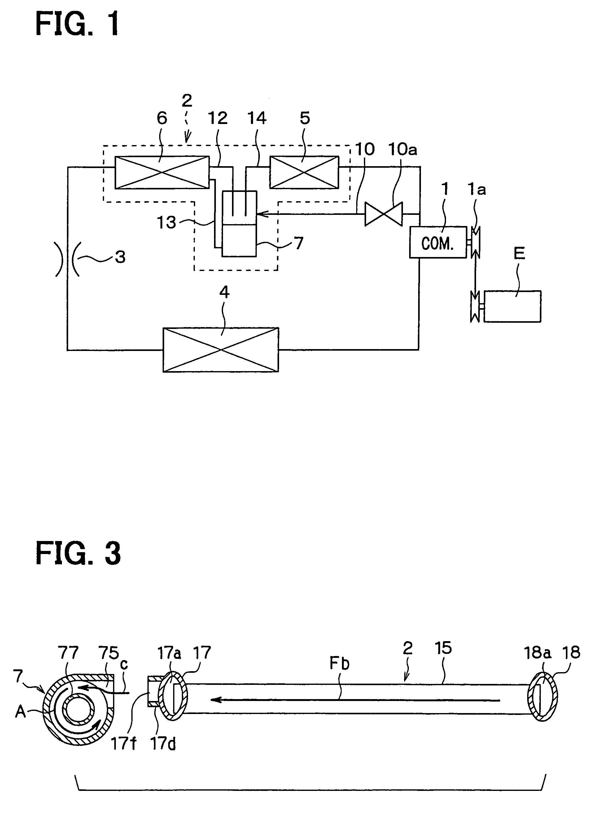
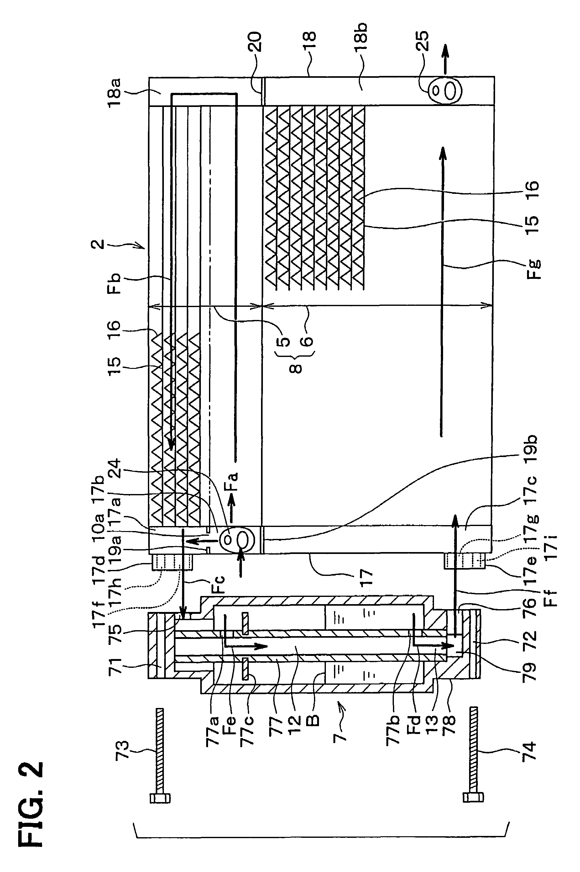
[0042]The first embodiment of the present invention will be now described with reference to FIGS. 1–3. In the first embodiment, a refrigerant cycle system shown in FIG. 1 is typically used for a vehicle air conditioner. In FIG. 1, a compressor 1 is driven by a vehicle engine E through a solenoid clutch 1a and a belt hung thereon. High-pressure and high-temperature refrigerant is discharged from the compressor 1, and is circulated into a separator-integrated condenser 2. In the condenser 2, the refrigerant is heat-exchanged with and cooled by outside air, and is condensed. The condenser 2 is disposed at a portion to be cooled by receiving running wind in a vehicle running. Specifically, the condenser 2 is disposed at a front area in an engine compartment, and is cooled by the running wind and air blown by a cooling fan (not shown).

[0043]A decompression device 3 decompresses refrigerant after passing through the condenser 2 to a low-pressure and gas-liquid refr...

second embodiment

[0065](Second Embodiment)

[0066]In the above-described first embodiment, the gas-liquid separator 7 is fixed by using the bolts 73, 74 to the left header tank 17 of the condenser 2. However, in the second embodiment, as shown in FIG. 4, the gas-liquid separator 7 is integrally brazed to the left header tank 17 of the condenser 2. Specifically, the gas-liquid separator 7 has a flat outer-wall surface on a side having the refrigerant inlet 75. That is, the gas-liquid separator 7 has a flat outer-wall surface that is bonded to the left header tank 17 by the brazing. The gas-liquid separator 7 is integrally brazed to the left header tank 17 while its flat outer-wall surface contacts an outer wall surface of the left header tank 17. Therefore, in the second embodiment, the components such as the connection joints 17d, 17e and the bolts 73, 74 in the first embodiment can be eliminated, thereby simplifying the construction, and eliminating screwing work of the bolts 73, 74. In the second em...

third embodiment

[0067](Third Embodiment)

[0068]In the above-described first and second embodiments, the liquid-refrigerant return passage 13 into which a part of liquid refrigerant stored in the gas-liquid separator 7 flows, is connected to the inlet side of the second heat-exchanging portion 6. However, in the third embodiment, as shown in FIG. 5, the liquid-refrigerant return passage 13 is connected to the outlet side of the second heat-exchanging portion 6. Further, as in the second embodiment, the gas-liquid separator 7 is integrally brazed to the left header tank 17.

[0069]In the third embodiment, as shown in FIG. 6A, three partition plates 19a, 19b, 19c are arranged in the up-down direction in the left header tank 17 of the condenser 2, thereby partitioning the inner space of the left header tank 17 into four spaces 17a, 17b, 17c′, 17c″ in the up-down direction. The partition plates 19a, 19b, the upper space 17a and the intermediate space 17b in the third embodiment correspond to those in the f...


PUM


Abstract

A refrigerant cycle system includes a first heat-exchanging portion for condensing gas refrigerant discharged from a compressor, a gas-liquid separator into which all of refrigerant after passing through the first heat-exchanging portion and a part of gas refrigerant discharged from the compressor are introduced, and a second heat-exchanging portion for cooling and condensing refrigerant flowing from the gas-liquid separator. Because all of the condensed refrigerant from the first heat-exchanging portion is introduced into the gas-liquid separator, a passage area of a gas refrigerant introduction passage for introducing gas refrigerant from the compressor into the gas-liquid separator can be set relatively large. Therefore, a dimension difference of the gas refrigerant introducing passage in manufacturing is not greatly affected to an adjustment of a liquid refrigerant amount in the gas-liquid separator.

Description

CROSS-REFERENCE TO RELATED APPLICATION[0001]This application is related to and claims priority from Japanese Patent Applications No. 2002-315799 filed on Oct. 30, 2002, No. 2003-27049 filed on Feb. 4, 2003 and No. 2003-39924 filed on Feb. 18, 2003, the contents of which are hereby incorporated by reference.BACKGROUND OF THE INVENTION[0002]1. Field of the Invention[0003]The present invention relates to a refrigerant cycle system for a vehicle air conditioner and the like. More particularly, the present invention relates to a separator-integrated condenser including first and second heat-exchanging portions and a gas-liquid separator.[0004]2. Description of Related Art[0005]For example, in a refrigerant cycle system disclosed in U.S. Pat. No. 6,427,480 (corresponding to JP-A-2002-323274), a condenser 302 includes first and second heat-exchanging portions 305, 306 and a gas-liquid separator 307 disposed between the first and second heat-exchanging portions 305, 306, as shown in FIG. 19...

Claims


Application Information

Patent Timeline
Patent Type & Authority Patents(United States)
IPC IPC(8): F25B39/04F25B31/00F25B41/00F25B43/00F25B5/00F25B40/02F25B41/06
CPCF25B39/04F25B41/06F25B40/02F25B2339/0441F25B2339/0442F25B2600/2501F25B2339/0445F25B2339/0446F25B2400/02F25B2400/23F25B2339/0444F25B41/30
Inventor YAMADA, ETSUHISAITO, SHIGEKIHOTTA, TERUYUKIYAMANAKA, YASUSHI
Owner DENSO CORP
Why Eureka
Try Eureka