Seat with temparature control and ventilation and safety system for a vehicle

a technology of vehicle seat and temperature control, which is applied in the direction of domestic cooling equipment, heating types, instruments, etc., can solve the problems of local over-cooling of users, health hazards, and disadvantages, and achieve the effects of improving ventilation, drying, and improving comfor

Inactive Publication Date: 2004-06-24
LEAR CORP
View PDF8 Cites 61 Cited by
  • Summary
  • Abstract
  • Description
  • Claims
  • Application Information

AI Technical Summary

Benefits of technology

0008] A principal purpose with the present invention is thus to provide an enhanced cooling, drying, temperature control and ventilation of a vehicle seat comprising a cooling device, where the disadvantages stated above are eliminated and which provides a surface temperature and surface dryness that during the adjustment becomes more comfortable for the traveller. This purpose is achieved by means of a device of a kind mentioned in the preamble, which characteristics are disposed in the appended claim 1, where the seat comprises an electrical heater and a detector unit in connec

Problems solved by technology

A problem for previously known cooling devices relates to the desire that respective seat has to have an accurately adjusted temperature and dryness on its surface, i.e. on the surface that the traveller in the vehicle senses.
Although this previously known system normally provides a reliable cooling and dryness on the surface of a vehicle seat, it is, however, afflicted with certain disadvantages.
Such a disadvantage relates to the fact that previously known systems, timer controlled or manually controlled, with a cooling element and a fan, provides a rather uncontrolled cooling and drying of the seat, due to the fact that the cooling via the cool airflow almost exclusively takes place by convection, which may lead to a local over-cooling of the user which in itself is a health hazard.
A furt

Method used


Image

  • Seat with temparature control and ventilation and safety system for a vehicle
  • Seat with temparature control and ventilation and safety system for a vehicle
  • Seat with temparature control and ventilation and safety system for a vehicle

Examples


Embodiment Construction

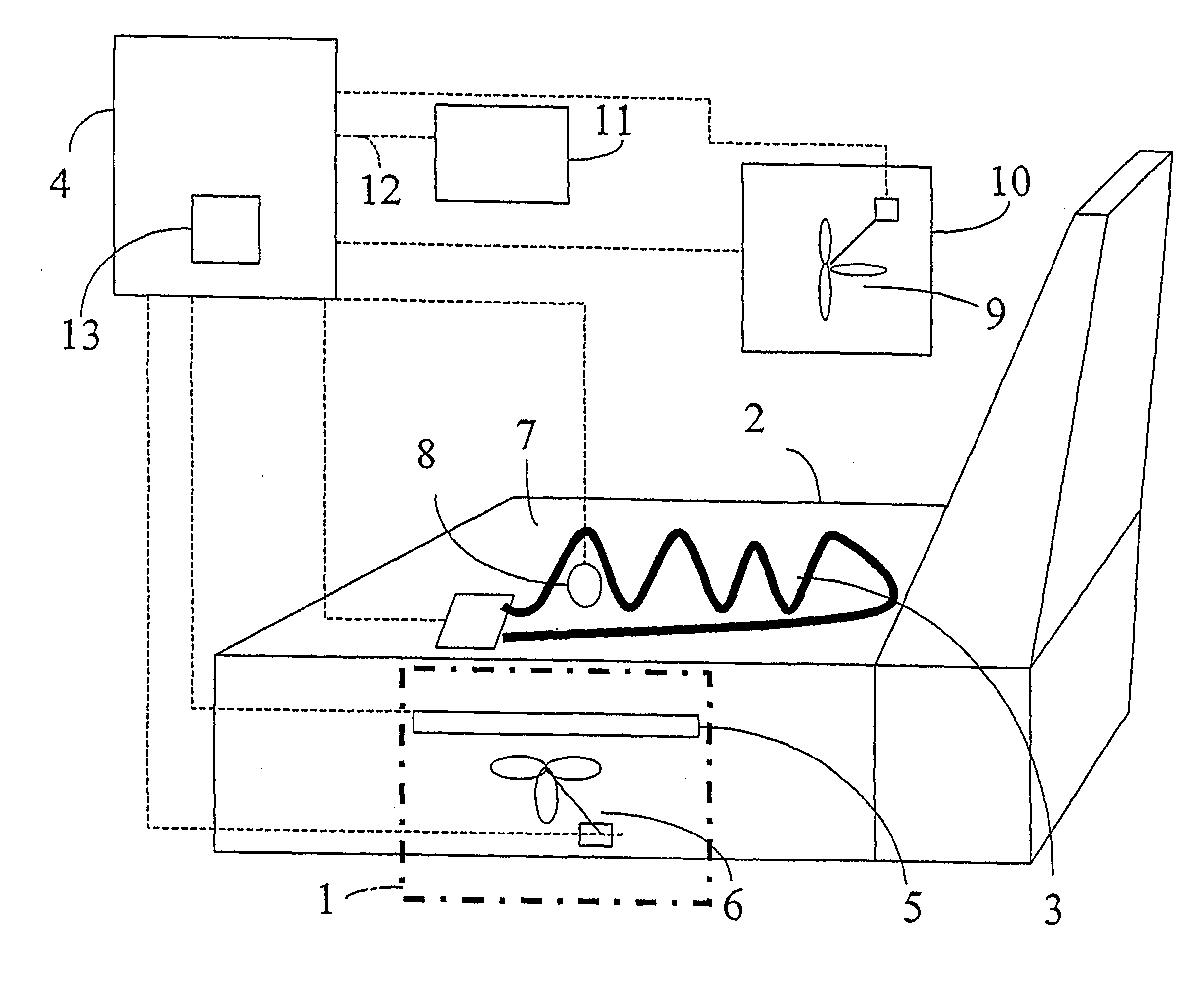
[0022] The embodiments which are described in connection with the explaining text are not to be regarded as examples of the invention solely, but also as a detailed description of the invention. The figures and the embodiments show principally the sitting surface of a seat, but the invention may in all its parts be exercised freely on all the seat parts of the seat, such as sitting surface and back parts. The invention may also be used only for ventilation of the seat, i.e. when cooling is lacking. Ventilation is often more important for the back part of the seat than for the sitting surface of the seat.

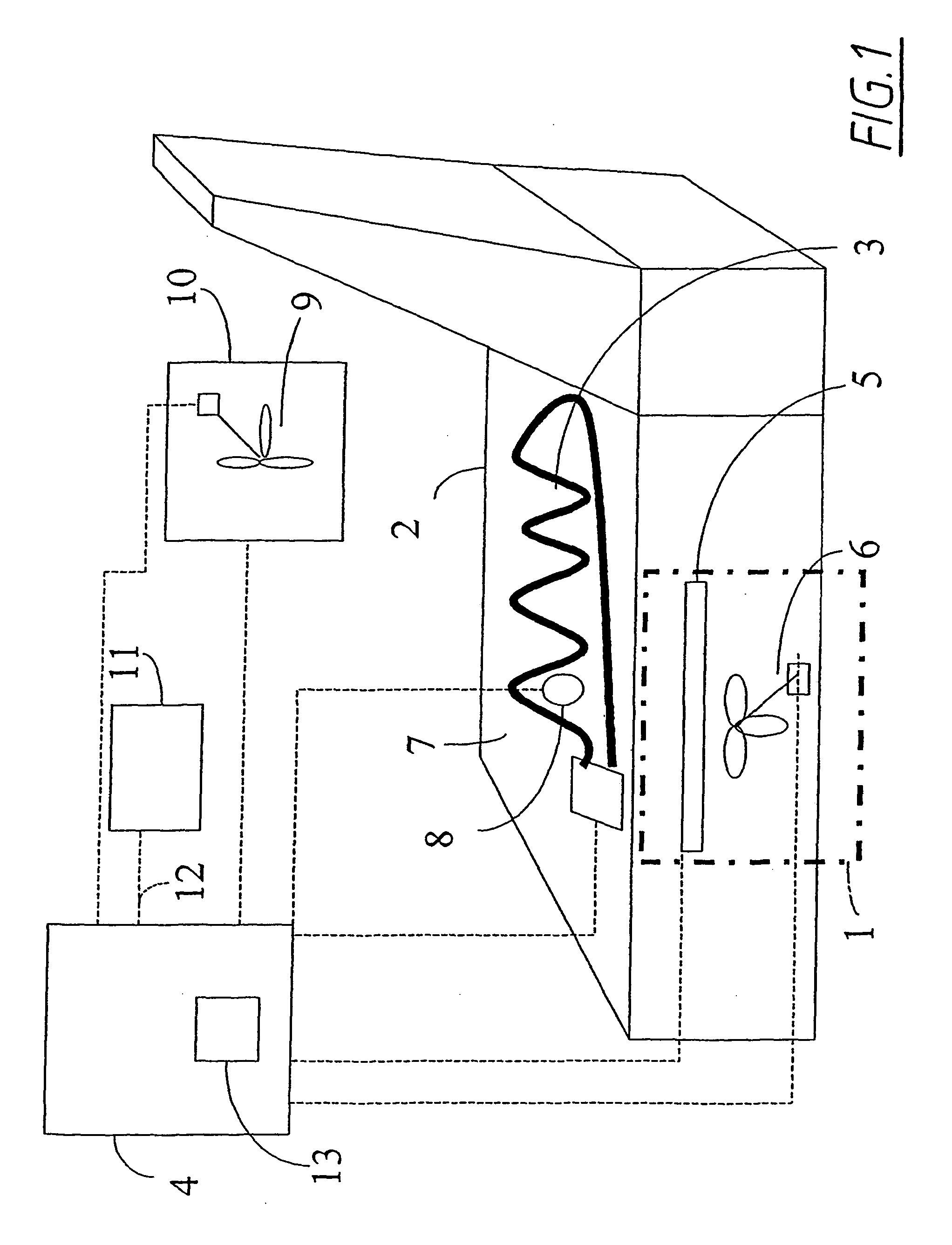
[0023] FIG. 1 shows a principal circuit diagram for a device according to a first embodiment of the invention. According to the first embodiment; the invention is intended to be used in connection with a cooling device 1 (shown as a dashed square) for a seat 2 in a vehicle and en electrical heater 3 for heating of the seat 2. The figure shows a control unit 4 on principle, which inte...


PUM


Abstract

Methods and apparatus for controlling the temperature of a seat such as a vehicle seat are disclosed. The apparatus includes an electrical heater disposed in the seat, a cooling unit such as a cooling element and a fan, a detector for detecting the temperature associated with the electrical heater, and a controller for controlling the electrical heater and the cooler based upon the detected temperature and upon the humidity algorithm comprising a predetermined set of calculations of the humidity of air at different temperatures.

Description

[0001] The present invention relates to a device and a method, respectively, for cooling of a seat, according to the preamble of the appended claim 1 and 13, respectively. In particular, the invention's main application is in connection with cooling and / or ventilation of electrically heatable seats for travellers in a vehicle.[0002] By reasons of comfort and security, ventilation and / or cooling of seats in for example vehicles, is used. The driver's seat as well as the other seats in the vehicle may thus be arranged to be cooled by means of special cooling devices, for example in the form of electrical Peltier elements, or by means of a fan device that blows on the current surface, or a combination of these. Such a cooling element or fan may be placed in the seat or in the backrest of respective seat when it is manufactured. Further, the cooling element and the fan, respectively, are connected to a current supply unit that supplies current The control systems according to previously...

Claims


Application Information

Patent Timeline
IPC IPC(8): A47C7/74B60H1/00B60H1/03B60H1/34B60N2/02B60N2/56B60N2/90G05D23/19G05D27/02
CPCB60H1/00285B60N2/0244B60N2/5635G05D27/02B60N2/5692B60N2002/0268B60N2/5685A61P35/00B60N2/0268
Inventor FRISTEDT, TOMMYJOSEFSSON, DANIEL
Owner LEAR CORP
Why Eureka
Try Eureka