Process for producing spiral membrane element

Inactive Publication Date: 2004-07-01
NITTO DENKO CORP
View PDF11 Cites 16 Cited by
  • Summary
  • Abstract
  • Description
  • Claims
  • Application Information

AI Technical Summary

Problems solved by technology

However, the method which includes mere formation of a line or broken line has had a drawback that creases are not sufficiently formed and this is apt to cause distortion in the later step of winding or the like, resulting in "wrinkling" or "breakage".
The precision of crease straightnes

Method used


Image

  • Process for producing spiral membrane element
  • Process for producing spiral membrane element
  • Process for producing spiral membrane element

Examples


Embodiment Construction

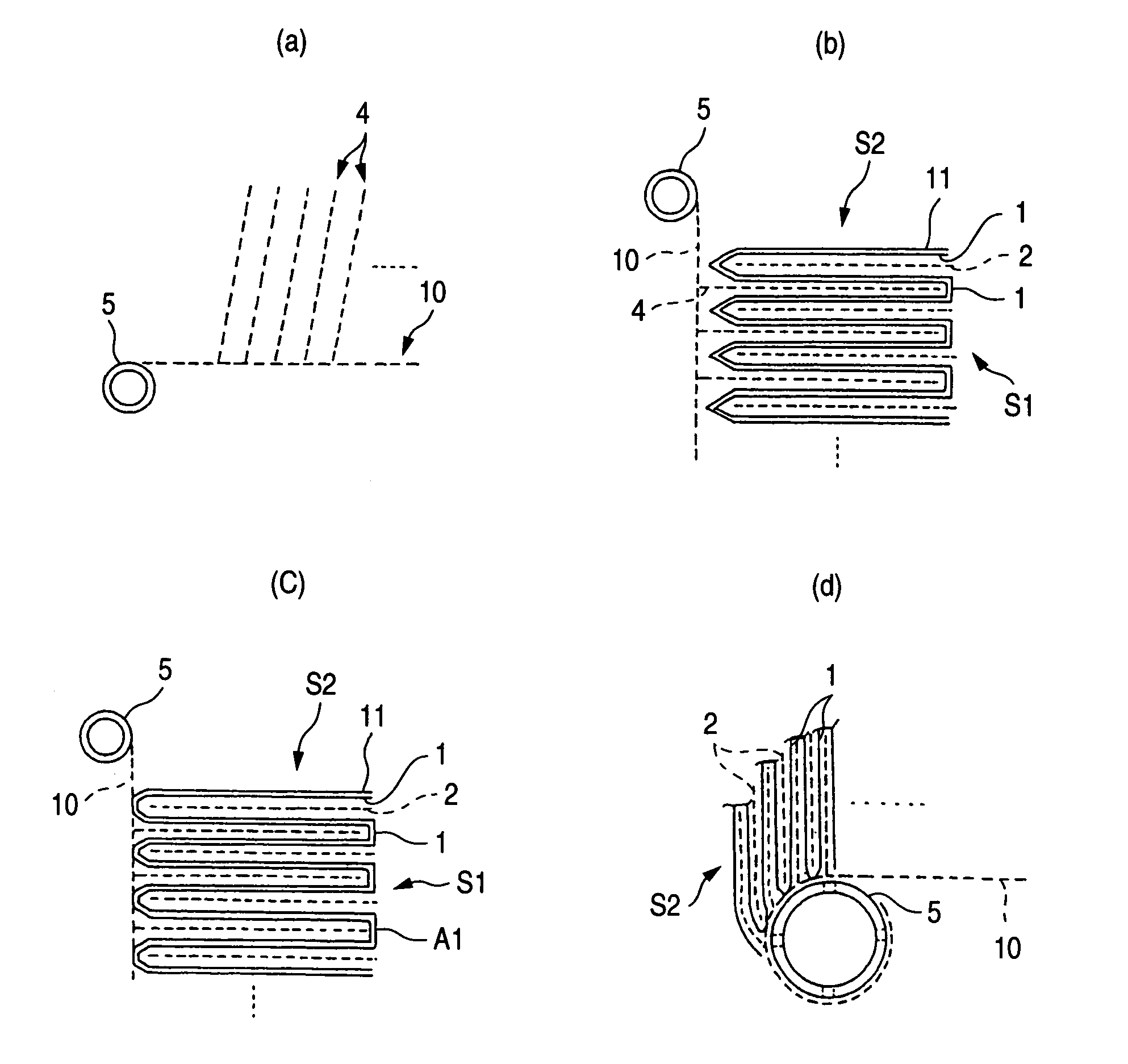
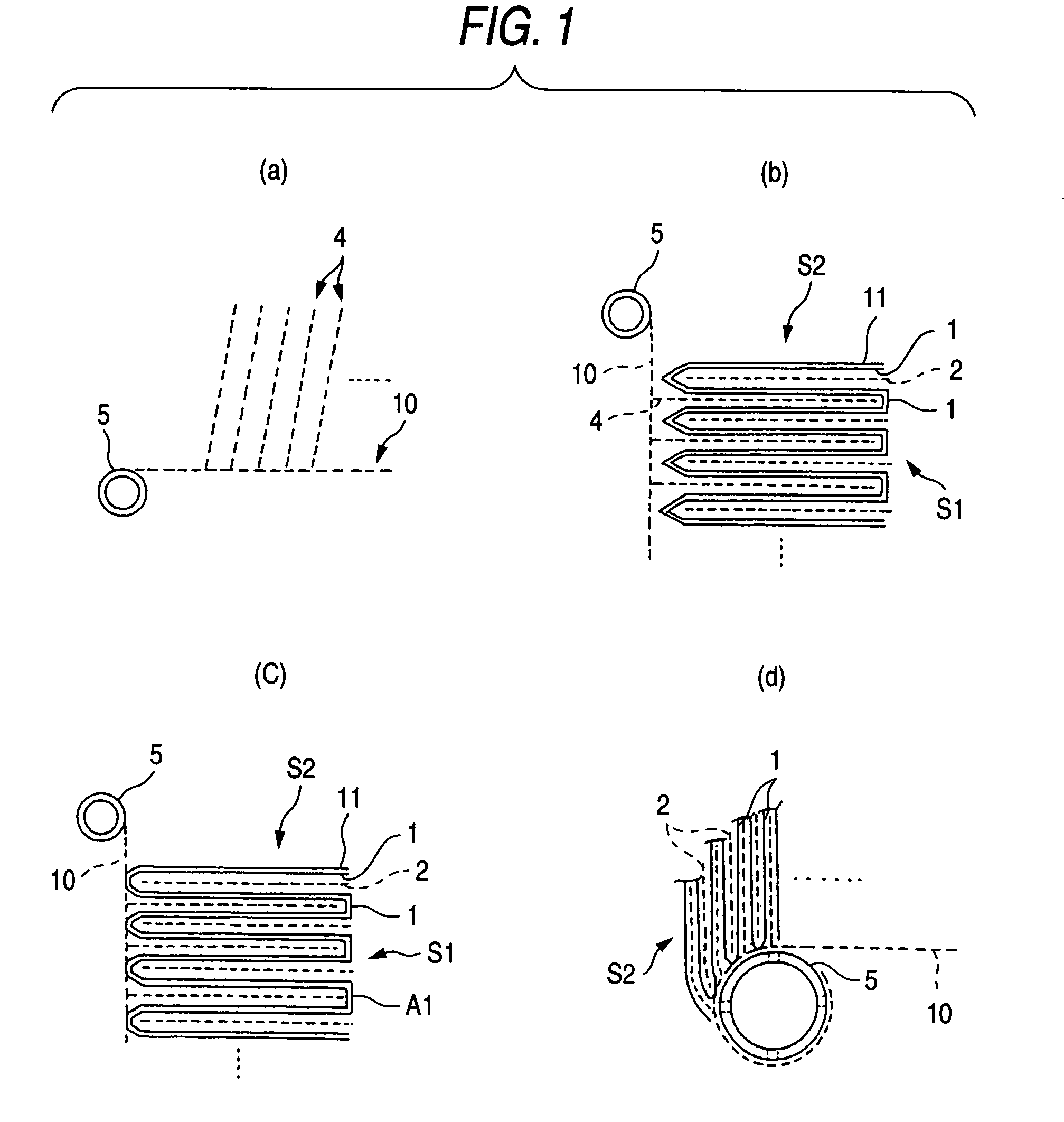
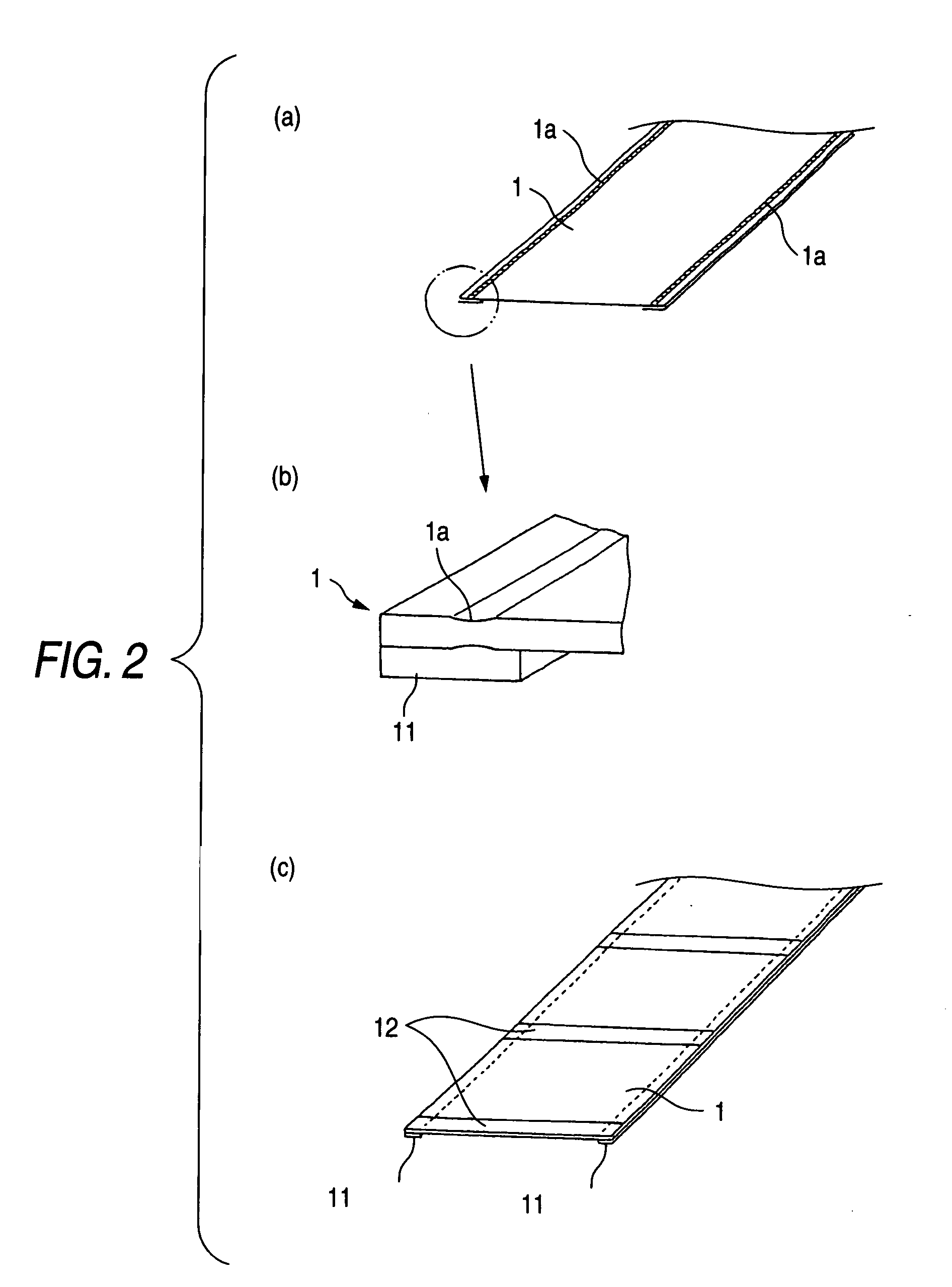
[0078] A 924 mm-wide membrane (NTR-759HR) manufactured by Nitto Denko Corp. was unwound and, simultaneously therewith, 5 mm heat sealing was continuously conducted in a width of 10 mm from each side edge. A fusion-bondable tape having a width of 20 mm was applied to the edge of the permeation side of each fusion-bonded part at a pressure of 0.05 MPa while avoiding wrinkling. It was ascertained that no wrinkles were formed. A PET tape NO. 31B having a width of 50 mm (manufactured by Nitto Denko Corp.) was applied to the feed side of the membrane at the same interval of 750 mm in the length direction while avoiding wrinkling. After the tape application, a metallic edged tool having a width of 0.5 mm and a mold as a receiving tool were used to form a line at a pressure of 200 N in each part to be creased. A feed-side passage material made of PP and having a width of 924 mm was cut into 750 mm beforehand. The cut feed-side passage materials were fixed alternately to the parts to which t...


PUM


Abstract

A process for spiral membrane element production is disclosed in which creases are stably and sufficiently formed to thereby enable the later step of winding or the like to be smoothly conducted while eliminating the "wrinkling" or "breakage" caused by the distortion of creased parts. The process comprises the step of forming a multilayer structure S2 comprising a membrane 1 which has been folded, a feed-side passage material disposed on the feed side of the folded membrane 1, and a permeation-side passage material disposed on the permeation side of the folded membrane 1 and the step of spirally winding at least the multilayer structure S2 on a perforated core tube 5, wherein the folded membrane 1 is obtained by forming beforehand in a membrane a folding initiation part L2 reduced in bending resistance along each of folding lines L1 for the membrane, folding the membrane 1 at the folding initiation parts L2, and heating and pressing the membrane 1 during and/or after the folding.

Description

[0001] The present invention relates to a process for producing a spiral membrane element for separating a specific ingredient from various fluids (liquids or gases). More particularly, the invention relates to an improved method of creasing a membrane for use in spiral membrane elements.DESCRIPTION OF THE RELATED ART[0002] Conventional spiral membrane elements are known to have a structure obtained by disposing a permeation-side passage material to the permeation side of two membranes, sealing three sides of the membranes to form a layered product of a bag shape, connecting a set of such layered products (membrane leaves) to a perforated core tube, and spirally winding the connected layered products together with feed-side passage materials interposed therebetween. An element is also known which employs two or more sets of such layered products (membrane leaves) so as to reduce the permeation-side passage length.[0003] The basic structure of the latter element generally comprises a...

Claims


Application Information

Patent Timeline
IPC IPC(8): B01D63/00B01D67/00B01D63/10B01D69/00
CPCB01D63/10
Inventor IRIE, KAORUINAGAKI, TOMOHIROOGURISU, TATSUYA
Owner NITTO DENKO CORP
Why Eureka
Try Eureka