Electric power plant with adjustable array of fuel cell systems

a fuel cell and array technology, applied in the direction of fuel cells, secondary cells charging/discharging, electric vehicles, etc., can solve the problems of large and heavy vrla battery banks, inability to tolerate even minor interruptions in power supply, and large vrla battery banks

Inactive Publication Date: 2004-07-01
BALLARD POWER SYSTEMS
View PDF38 Cites 73 Cited by
  • Summary
  • Abstract
  • Description
  • Claims
  • Application Information

AI Technical Summary

Problems solved by technology

Consumers who rely on electronic equipment, for example, cannot tolerate even minor interruptions in power supply.
For example, particularly in applications requiring extended battery run time (e.g., >4 hr), VRLA battery banks are large and heavy.
A large battery bank requires a significant amount of indoor floor space for installation, which can be expensive.
In addition, the weight of the battery bank may require indoor floor space with increased loading capacity, further increasing costs.
Environmental regulations relating to the storage and operation of VRLA batteries also add to increased installation costs.
Operating and maintaining a generator further adds to the cost and complexity of systems employing them.
The described systems have several disadvantages relating to the supply of reactants to the fuel cells, the time it takes for the fuel cells to produce full power, and their surge demand capacity, for example.
On start-up, there is typically a delay until the fuel cells reach full operating power.
For this reason, back-up or UPS systems solely employing fuel cells are inadequate for some applications because they are not "instant on".
While this approach improves response time, it exacerbates hydrogen storage issues by significantly increasing hydrogen consumption.
In addition, operational lifetime of the power plant may be adversely affected compared to systems where the power plant is operated intermittently.
Fuel cells can be damaged if the load requirements exceed their maximum output.
This, in turn, undesirably increases the cost of the power plant.
In most instances it is prohibitively costly and operationally inefficient to employ a power supply capable of providing more power than required by the application.
It is also costly and inefficient to design, manufacture and maintain inventories of different power supplies capable of meeting the demand of each potential application (e.g., 1 kW, 2 kW, 5 kW, 10 kW, etc.).

Method used


Image

  • Electric power plant with adjustable array of fuel cell systems
  • Electric power plant with adjustable array of fuel cell systems
  • Electric power plant with adjustable array of fuel cell systems

Examples


Embodiment Construction

[0133] FIGS. 24 and 25 are schematic illustrations of conventional back-up or UPS systems. In FIG. 24, power grid 502 normally supplies power to rectifier 504 and other AC loads such as lighting, HVAC, and other equipment. Rectifier 504 converts the AC power from the grid to DC power and directs it to DC power distribution panel 512. From panel 512 power may be directly supplied to compatible voltage DC loads. Power may also be directed to DC / DC converter 514, which converts it to a different voltage for use by other DC loads; or to inverter 516, which converts the power to an AC source for use by AC loads. If the grid fails, power is supplied by battery bank 518 to panel 512. Battery bank 518 will be sized to provide adequate power to critical loads for the desired amount of time. Standby generator 520 is brought online by switch 152 to provide power if the grid is interrupted for an extended period.

[0134] In FIG. 25, power from the grid is normally supplied from AC power distribut...


PUM

PropertyMeasurementUnit
timeaaaaaaaaaa
voltagesaaaaaaaaaa
output poweraaaaaaaaaa

Abstract

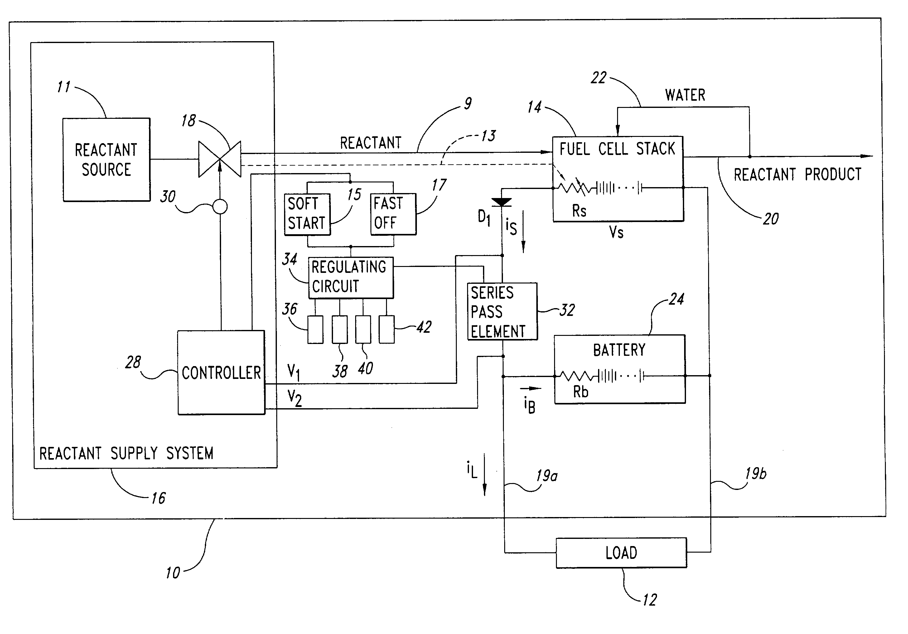
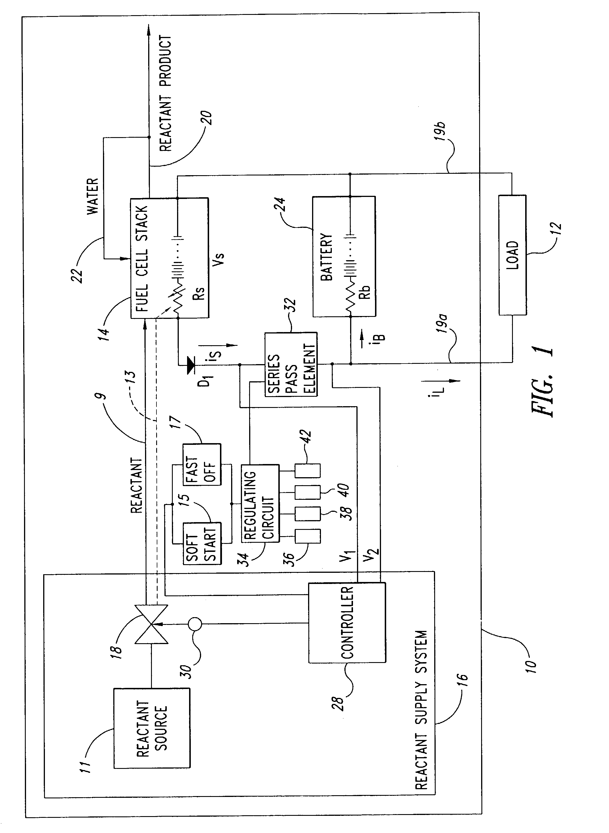
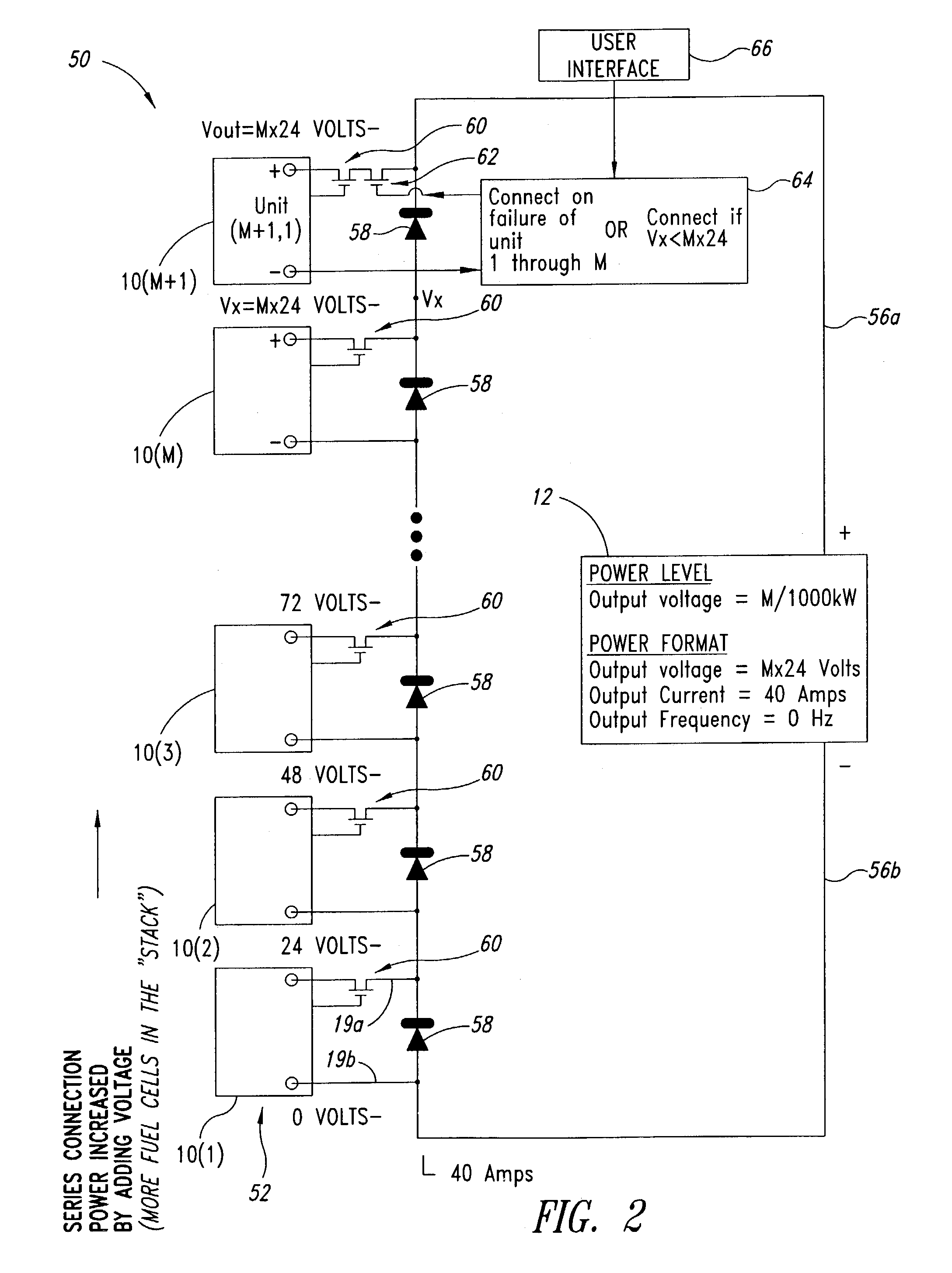
An electric power plant includes an array of fuel cell systems. The fuel cell systems are electrically couplable in series and / or parallel combinations to provide a variety of output powers, output current and / or output voltages. The fuel cell systems are "hot swappable" and redundant fuel cell systems may automatically replace faulty fuel cell systems to maintain output power, current and / or voltage.

Description

[0001] 1. Field of the Invention[0002] This disclosure generally relates to power supplies, for example, fuel cell systems, and to electrical power storage devices, for example, batteries and / or ultracapacitors.[0003] 2. Description of the Related Art[0004] Fuel cells are known in the art. Fuel cells electrochemically react a fuel stream comprising hydrogen and an oxidant stream comprising oxygen to generate an electric current. Fuel cell electric power plants have been employed in transportation, portable and stationary applications.[0005] Stationary and portable applications include distributed power generation, back-up power, peak power, and uninterruptible power supply (UPS) systems. Distributed power generation relates to providing electrical power to residential, commercial and / or industrial customers instead of, or as a supplement to, the utility power grid. Power plants in such applications typically operate continuously. They are particularly suited to situations where the ...

Claims


Application Information

Patent Timeline
Patent Type & Authority Applications(United States)
IPC IPC(8): H01M8/00H01M8/04H01M8/24H01M16/00
CPCH01M8/04007H01M8/04089H01M8/04753H01M8/0488H01M8/0491Y02E60/50H01M8/0494H01M8/04947H01M8/249H01M16/003H01M8/04917
Inventor PEARSON, MARTIN T.
Owner BALLARD POWER SYSTEMS
Why Eureka
Try Eureka