[0004] The fuel injection valve of the invention having the definitive characteristics of claim 1 has the
advantage over the prior art that both the inner and the outer valve needle can be triggered via only a single control valve. A control chamber is embodied in the housing and communicates with the high-pressure conduit and furthermore with a control pressure chamber. Through the pressure in the control chamber, a closing force is exerted at least indirectly on the outer valve needle. In the housing, there is a control valve by which the control chamber can be made to communicate with a leak fuel chamber, so that the pressure in the control chamber and, because of the communication with the control chamber, in the control pressure chamber as well can be lowered to markedly below the
injection pressure via the control valve, so that the closing force on the inner and outer valve needle can be controlled. Via a suitable switching characteristic of the control valve and suitably dimensioned inlets and outlets from the control chamber and of its communication with the control pressure chamber, a separate triggering of the outer valve needle, or selectively of both valve needles, can be achieved.
[0005] In an advantageous feature of the subject of the invention, the control valve has a valve chamber, which communicates with the control chamber, and also has a valve member, which is controlled by an
actuator. The
actuator is advantageously embodied as an electric
actuator and in particular as a piezoelectric actuator. As a result, the valve member can be controlled precisely, and the valve member can be moved directly to the desired position.
[0006] In a further advantageous feature, in a first switching position, the valve member cooperates with a first
valve seat, and in a second switching position it cooperates with a second
valve seat; in the first switching position, the valve chamber is sealed off from the leak fuel chamber, and in the second switching position it communicates with the leak fuel chamber. By means of this valve member, the pressure in the control chamber can be controlled precisely and without any significant
time lag.
[0007] In a further advantageous feature, the valve chamber of the control valve can be made to communicate with the high-pressure conduit via a connecting conduit, and when the valve member is in contact with the second valve seat, it closes the connecting conduit. Upon relief of the control chamber, the connecting conduit thus becomes inoperative and does not impede the further function of the pressure regulation in the control chamber. Upon actuation of the control valve and upon motion of the valve member toward the first valve seat, the high-pressure conduit is uncovered, and fuel can flow at the
injection pressure into the valve chamber and from there into the control chamber. As a result, after the end of the injection, a
high pressure is built up very quickly in the control chamber, so that a strong closing force on the outer valve needle and thus also on the inner valve needle results.
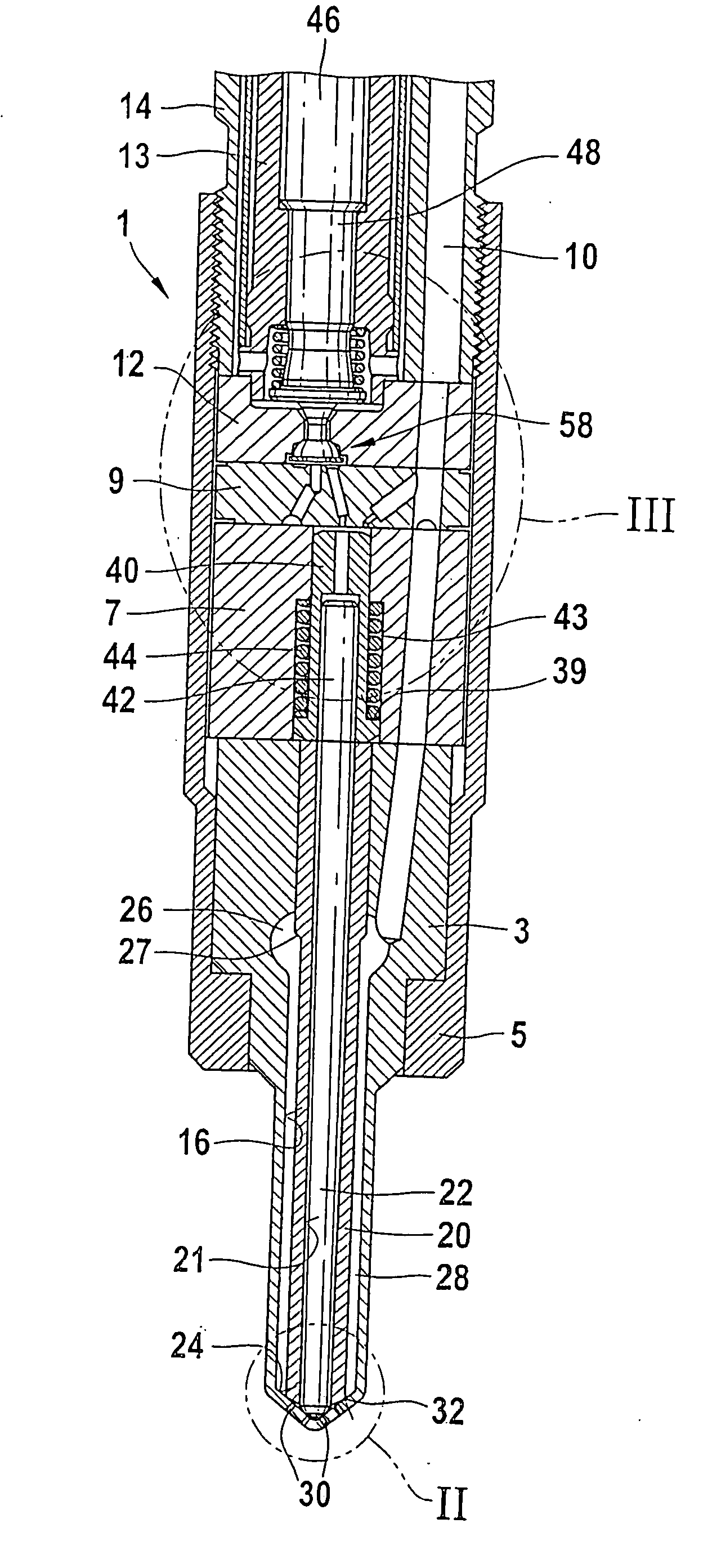
[0008] In a further advantageous feature, an outer pressure
piston is disposed in a housing; it communicates with the outer valve needle, and its end face defines the control chamber. In this way, as a result of the pressure in the control chamber, a hydraulic force on the end face of the outer pressure
piston is produced, so that a closing force is exerted on the outer valve needle. Because of the separation of the function of the pressure face subjected to pressure and of the valve needle, the two parts can be optimized separately from one another.
[0009] In still another advantageous feature, the outer pressure
piston, in the opening
stroke motion of the outer valve needle, comes to rest on a wall of the control chamber, interrupting the communication of the control chamber with the high-pressure conduit. As a result, when the fuel injection valve is open, fuel no longer flows into the control chamber, and thus the leak fuel losses of the fuel injection valve are minimized.
[0010] In another advantageous feature, the control pressure chamber is embodied in the outer pressure piston and communicates with the control chamber through a bore in the outer pressure piston. This construction allows direct triggering of the inner valve needle, which is located inside the outer valve needle, and furthermore results in a very space-saving construction.
[0011] In an advantageous feature, a pressure markedly lower than the injection pressure, this lower pressure preferably being
atmospheric pressure, prevails in the leak fuel chamber. The lower the pressure in the leak fuel chamber, the greater are the pressure differences from the injection pressure, so that correspondingly greater forces on the inner and outer valve needle can also be achieved, and hence shorter switching times.

