Well jet device for well testing and development and operating method for said well jet device

a technology of well jet device and well, which is applied in the direction of machines/engines, fluid removal, borehole/well accessories, etc., can solve the problems of reducing the efficiency of the work performed in order to intensify oil production, and the operation does not enable the full utilization of the device potential, so as to improve the efficiency of the operation of the well jet device

Inactive Publication Date: 2004-07-15
KHOMYNETS ZINOVIY DMITRIEVICH
View PDF7 Cites 22 Cited by
  • Summary
  • Abstract
  • Description
  • Claims
  • Application Information

AI Technical Summary

Benefits of technology

0010] The objective of this invention is to optimize the dimensions of various components of the construction of the well jet device and the sequence of operations when carrying out works on intensifying the well exploitation and, owing to it, to raise the efficiency of well jet device operation in developing and testing wells.

Problems solved by technology

But in some cases this is insufficient for obtaining reliable information on the well condition, which reduces the efficiency of works performed in order to intensify oil production.
But, the known well jet device and the method of operation do not enable to exploit the potential of the device in full due to non-optimal sequence of operations and dimension relations of various structural elements of the well jet device.

Method used


Image

  • Well jet device for well testing and development and operating method for said well jet device
  • Well jet device for well testing and development and operating method for said well jet device
  • Well jet device for well testing and development and operating method for said well jet device

Examples


Embodiment Construction

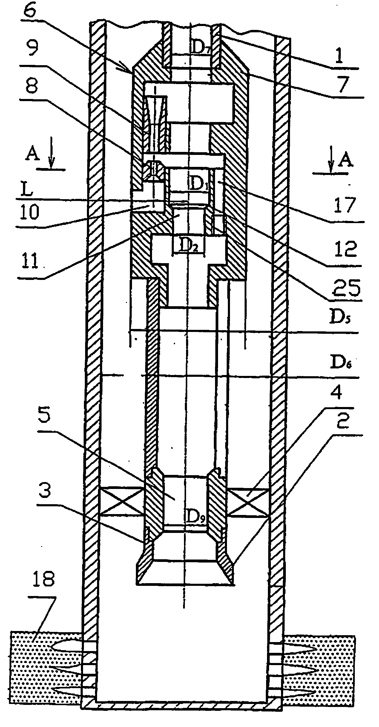
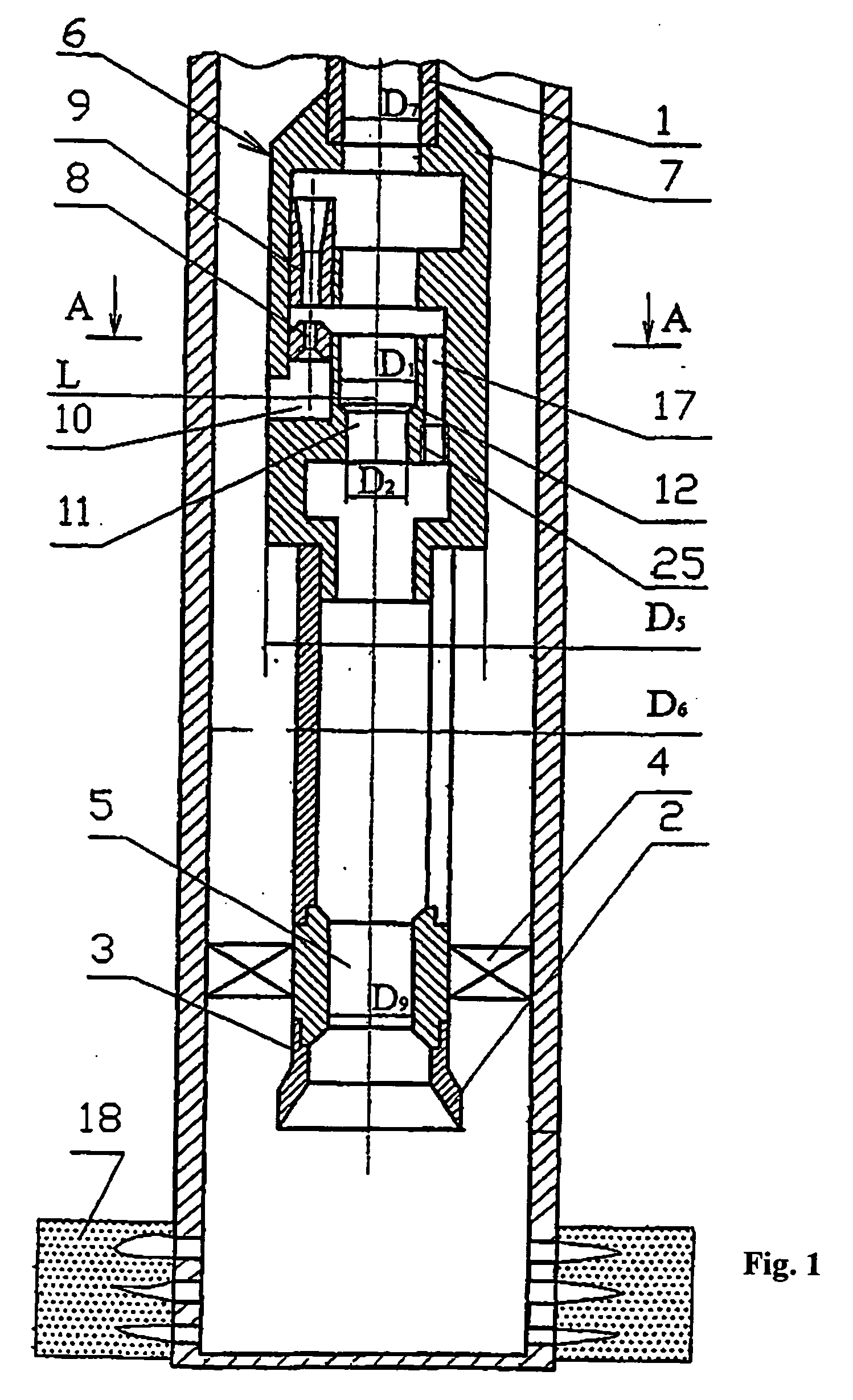
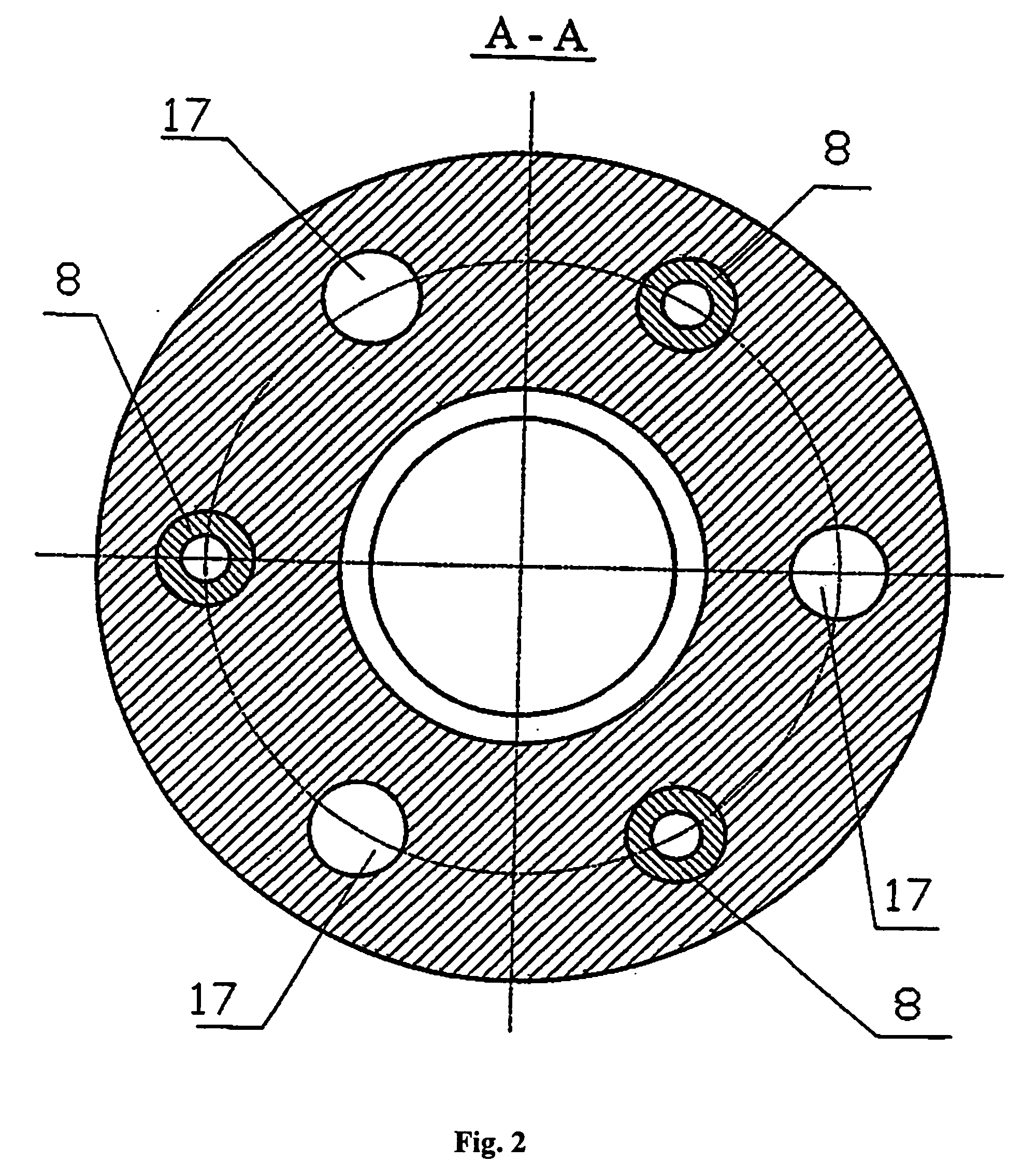
[0022] The proposed well jet device for testing and developing wells, which is served to implement the described method, comprises, installed on the piping string 1 down-top, the input cone 2 with the shank 3, the packer 4 with the through passage 5, and the jet pump 6, in the body 7 of which one or several active nozzles 8 are axially arranged, with the respective mixing chamber 9 and the passage 10 for supplying the active medium. In the body 7 of the jet pump 6 the stepped through passage 11 is made with the mounting seat 12 between steps for installing the sealing assembly 13 having the axial channel 14. The said device being provided with the transmitter and receiver-transducer of physical fields 15, which is arranged on the side of the jet pump 6 for entry of the medium pumped out of the well and installed on the cable or wire 16 fed through the axial passage 14 of the sealing assembly 13. The output side of the jet pump 3 is connected to the piping string 1 above the sealing ...


PUM


Abstract

The invention relates to jet devices for extracting oil from wells and intensifying the oil influx rate. An output cone, a packer and a jet pump are mounted on a tubing string. One or several active nozzles are arranged inside the pump body, and a stepped pass channel provided with a mounting seat for a pressure-sealing unit which is disposed between stages and several channels for supplying a pumped-out medium are embodied inside said pump body. The axes of the nozzles are disposed in a parallel position with respect to the axis of the pass channel at a certain distance therefrom. The inventive device is provided with a radiator and a receiver-transducer of physical fields mounted on a cable in such a way that it is replaceable by other instruments. Said cable passes through the axial channel of the sealing unit which is arranged in such a way that it is successively replaceable by functional inserts such as a testing and depression inserts etc. Said inserts are provided with mechanisms for bringing them to the pump body and for extraction therefrom. Mounting seats for back valves and plugs are embodied in the lower part of the channels for supplying the pumped-out medium. The dimension ratios of the elements of the inventive device are also disclosed. The aim of the invention is to optimise the dimensions of the elements of said device and increase the performance thereof.

Description

[0001] This invention relates to the field of pumping engineering, mainly to well jet devices for oil production and intensification of oil inflow from wells.PRIOR ART[0002] Known in the art is a well jet device comprising a jet pump installed on the piping string in the well and a transmitter and a receiver-transducer arranged below the jet pump (RU 2129671 C1).[0003] From the above source known is a method of operation of a well jet device, which includes lowering in the well a piping string with a jet pump, a packer and a transmitter and a receiver-transducer of physical fields, the latter being arranged below the jet pump.[0004] The known device and method enable to explore wells and pump various extracted media, e.g., oil, out of wells, at the same time exploring the well, the transmitter and receiver of physical fields being arranged with the possibility of moving back and forth along the well relative to the jet pump and the stratum.[0005] But in some cases this is insufficie...

Claims


Application Information

Patent Timeline
Patent Type & Authority Applications(United States)
IPC IPC(8): F04F5/10F04F5/02F04F5/44F04F5/46
CPCF04F5/10F04F5/464F04F5/44
Inventor KHOMYNETS, ZINOVIY DMITRIEVICH
Owner KHOMYNETS ZINOVIY DMITRIEVICH
Why Eureka
Try Eureka