Xray detector having tiled photosensitive modules and Xray system
Inactive Publication Date: 2004-07-15
HITACHI MEDICAL CORP
View PDF4 Cites 25 Cited by
Summary
Abstract
Description
Claims
Application Information
AI Technical Summary
This helps you quickly interpret patents by identifying the three key elements:
Problems solved by technology
Method used
Benefits of technology
Benefits of technology
[0016] To manufacture a plurality of lines of X-ray detectors to be mounted on the X-ray CT apparatus of a multi-slice type, a large semi-conductor wafer is necessary. When the semi-conductor wafer is larger, the price itself of the wafer is high. The number of detectors which can be manufactured from one semi-conductor wafer is reduced. A high technique for handling is required. The yield of manufacturing the detectors is decreased. The cost for manufacturing the X-ray detectors is high.
[0017] As a method for solving the problems, there is a method in which a plurality of X-ray detector modules provided with a small number of lines of the X-ray detecting elements 110 are close to each other for use. Such method can manufacture substantially multi-slice X-ray detector modules at relatively low cost.
[0019] As a method for solving such problem, Patent Document 1 (Japanese Laid-Open No. 2001-242253) proposes an X-ray detector which permits readout when an X-ray detector module is surrounded by other modules by performing wiring between a distribution module and an X-ray detector module for reading out a signal from the X-ray detector module using a space provided by cutting away part of a scintillator. The scintillator is provided with a cutaway part, lowering the X-ray detective efficiency in the photo-electric means.
[0021] To solve the above prior art problems, an object of the present invention is to provide an X-ray detector which can easily perform wiring connection between a photo-electric module and a distribution module or wiring connection between photo-electric modules adjacent to each other without making the cutaway part of the micro scintillator for wiring connection so as to realize a matrix construction having a large area without lowering resolution, causing a dead space and reducing X-ray detective efficiency.
[0025] In the space are provided wiring between a distribution module for reading out a signal from an X-ray detector module and the photo-electric module of the X-ray detector or / and wiring between the photo-electric modules adjacent to each other (The wirings are called module wiring means.). It is possible to realize an X-ray detector having a matrix construction having a large area without lowering resolution, causing a dead space and reducing X-ray detective efficiency when tiling a plurality of the X-ray detector modules without cutting away the scintillator unlike the prior art.
Problems solved by technology
The cost for manufacturing the X-ray detectors is high.
In this method, when the X-ray detector module is surrounded by other modules, a method for reading out a signal of the module is a problem.
Method used
Image
Click on the blue label to locate the original text in one second.
Reading with bidirectional positioning of images and text.
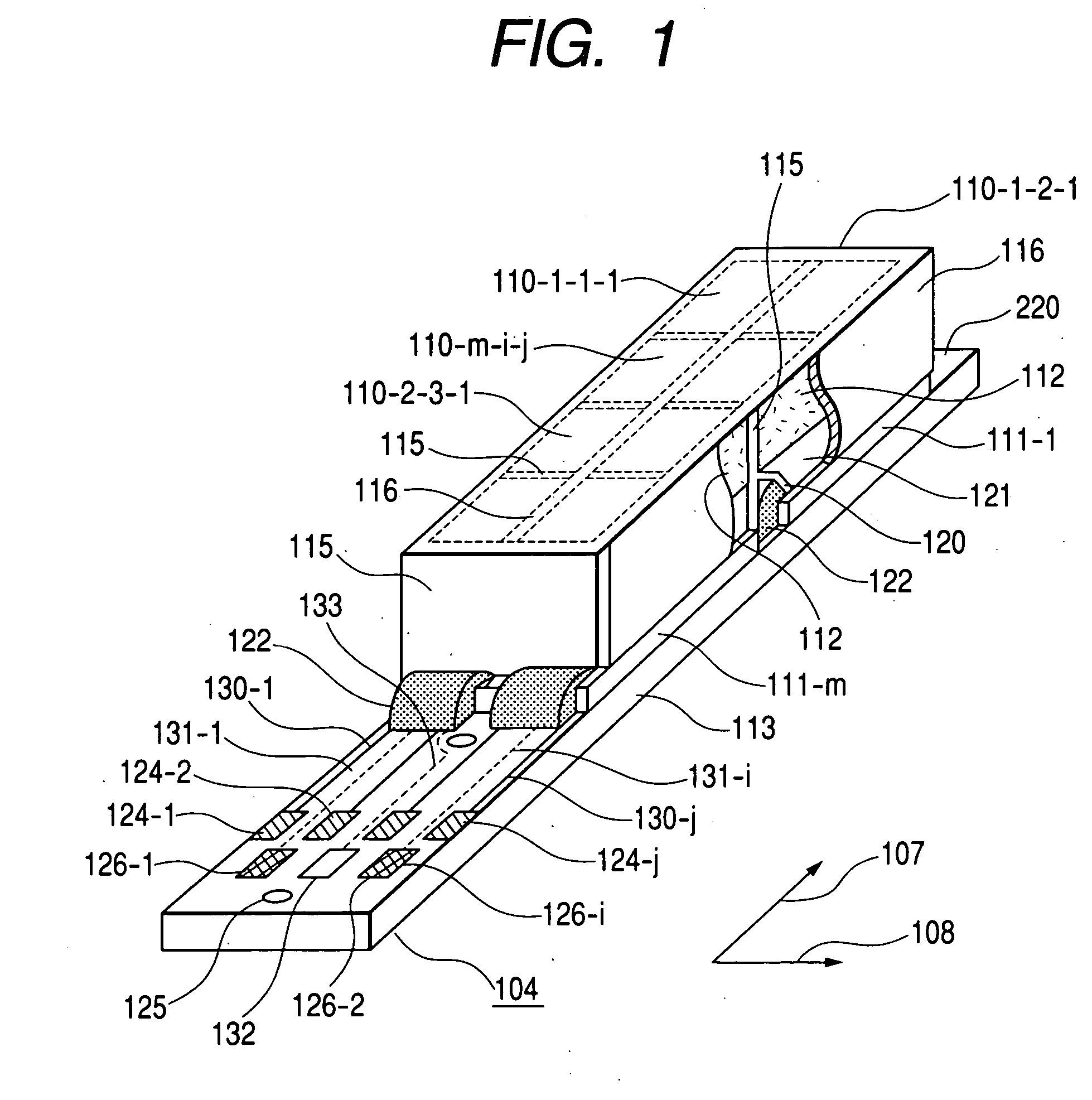
[0078] A construction example of the X-ray detector 104 as Example 1 of the present invention will be described using FIG. 1 and FIGS. 4 to 7.
[0079] FIG. 1 shows the construction of the X-ray detector 104 according to the present invention. In this example, for simplifying the description, for convenience, the X-ray detector 104 having two photo-electric modules 111 mounted on a distribution module 113 is shown. For simplifying the description, the X-ray detector 104 also has X-ray detecting elements 110 arrayed in four lines and two columns. The array of the number j of lines and the number i of columns of the X-ray detecting elements 110 constructing the X-ray detector 104 in the present invention is not limited to this example.
[0080] The X-ray detector 104 of FIG. 1 has a circuit module 113, photo-electric modules 111, transparent means 121 and scintillators 112. m (=1, 2) expresses an array number of the photo-electric modules 111...
[0132] FIG. 16 shows a circuit diagram of the X-ray detector 104 according to the present invention seen from the top. The X-ray detector 104 of this drawing shows the case of X-ray detecting elements 110 in four lines and two columns for simplifying the description.
[0133] The X-ray detecting element 110-m-i-j of the X-ray detector 104 has unillustrated scintillators 112-m-i-j, unillustrated transparent means 121-m-i-j, photo-electric means 114-m-i-j and switching elements 151-m-i-j, which are located in a matrix.
[0134] The source electrode of the switching element 151-m-i-j of the X-ray detecting element 110-m-i-j belonging to the same column i is electrically connected to an electrode pad for data line 126-i by a common data line 131-i. The gate electrode of the switching electrode 151-m-i-j of the X-ray detecting element 110-m-i-j belonging to the same line j is electrically connected to a vertical shift-resistor 190-m by an addres...
example 3
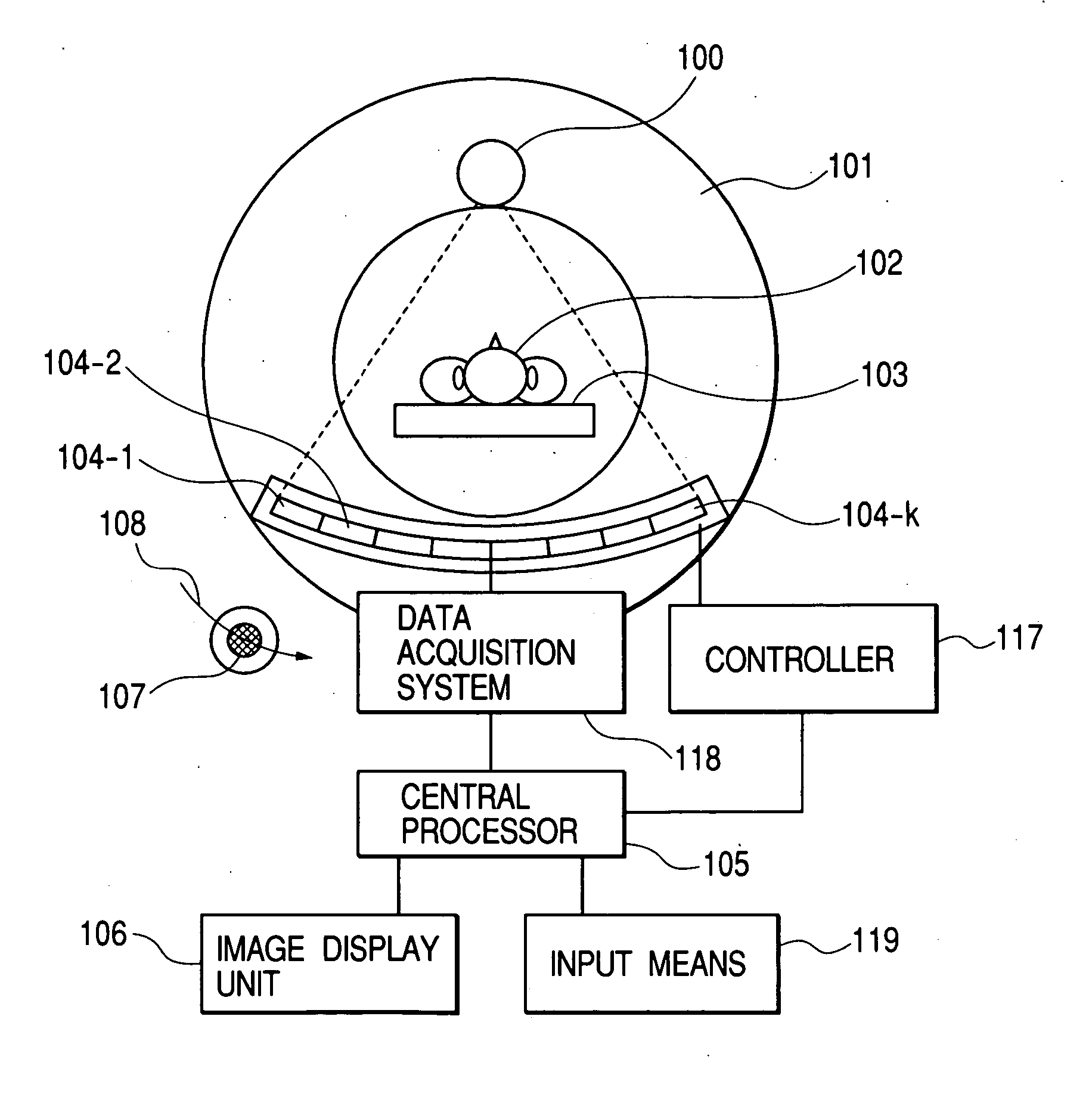
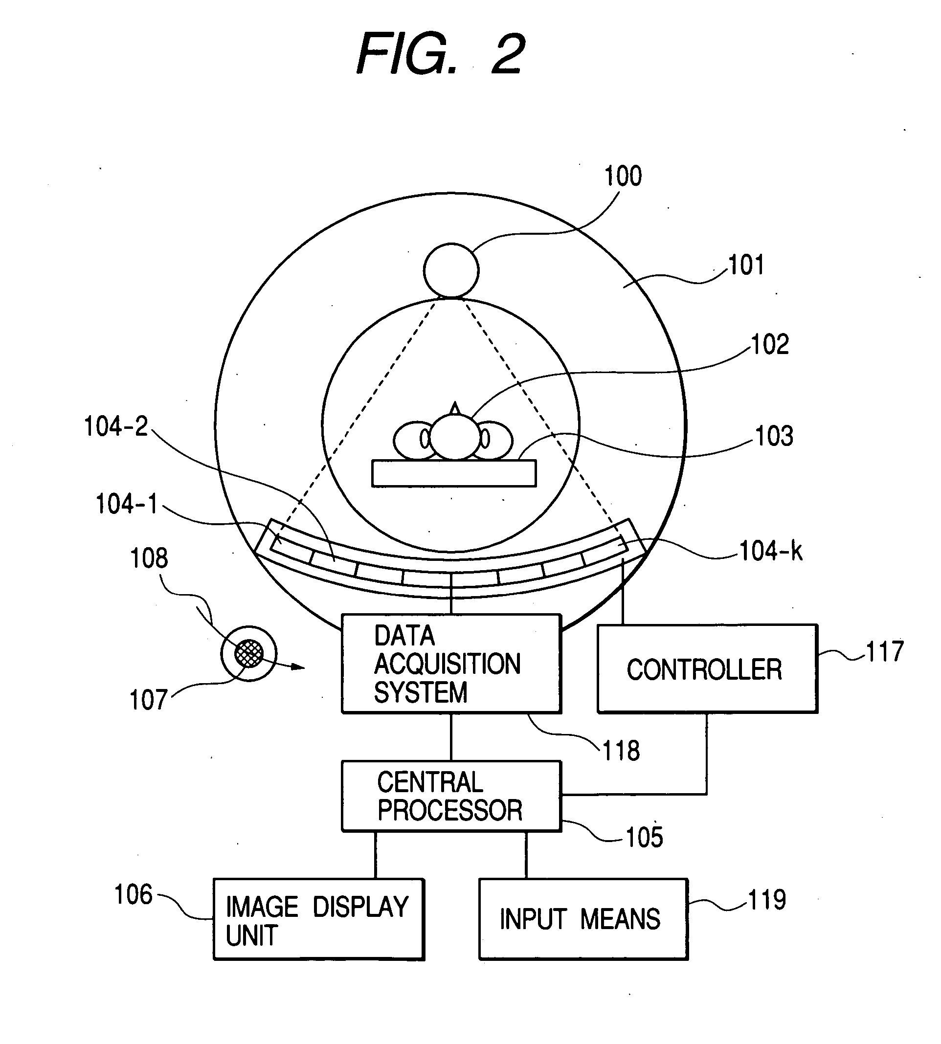
[0148] FIG. 20 shows an example of the configuration of the X-ray CT apparatus according to the present invention. The X-ray CT apparatus has an X-ray source 100, X-ray detectors 104, a data acquisition system (DAS) 118, a central processor 105, an image display unit 106, input means 119, a controller 117, a rotated gantry 101, and a bed 103.
[0149] The X-ray detectors 104 are described in Example 1 or 2. In FIG. 20, for simplifying the description, eight X-ray detectors are located in an arc. Actually, for example, 40 X-ray detectors are located.
[0150] One X-ray detector 104 is realized by pasting, in a slice direction, eight photo-electric modules 111 with X-ray detecting elements 110 in 24 columns in a slice direction 108 and in 256 lines in a slice direction 107. The size of the X-ray detecting element 110 is e.g., 1 mm.times.1 mm.
[0151] The X-ray source 100, the data acquisition system 118, the central processor 105, the image display unit 106, the input means 119, the controlle...
PUM
Abstract
There are provided an X-raydetector which can realize a larger area without lowering resolution and reducing X-ray detective efficiency when obtaining a matrix construction having a large number of X-ray detecting elements by tiling and a system using the same. An X-ray detector 104 has a construction in which a plurality of photo-electric modules 111 having a plurality of X-ray detecting elements 110 located in a two-dimensional manner are pasted onto a distribution module 113. The X-ray detecting element 110 has scintillators 112, transparent means 121 and photo-electric means 114. These are optically connected to each other. On the edge of the transparent means 121 on one of the photo-electric modules 111 mounted on the distribution module to be adjacent to each other is formed a cutaway part 120 so that the area of an output surface 211 outputting a light to the photo-electric means 114 is smaller than that of an incident surface 210 upon which a light is incident from the scintillators 112. A space caused by the cutaway part 120 is located wiring between the photo-electric module 111 and the distribution module 113 or wiring between the photo-electric modules 111 adjacent to each other.
Description
BACKGROUND OF THE INVENTION AND RELATED ART STATEMENT FIELD OF THE INVENTION[0001] The present invention relates to an X-ray detector and an X-ray system using the same. More specifically, the present invention relates to an X-ray detector of a two-dimensional (2D) array type which has X-ray detecting elements located in a matrix which irradiate an X-ray onto a scintillator to change it to an optical signal and further convert the optical signal to an electric signal for detection and an X-ray system which uses the same in an X-ray CT apparatus and an X-ray imaging system.[0002] The case of applying an X-ray detector to an X-ray CT apparatus will be described below as a representative example. The X-ray CT apparatus is an apparatus which can obtain a cross-sectional view of an object and is widely used in fields of medical and non-destructive inspection. The configuration of an X-ray CT apparatus as an example used in medical is shown in the schematic diagram of FIG. 2 and will be d...
Claims
Application Information
Patent Timeline
Application Date:The date an application was filed.
Publication Date:The date a patent or application was officially published.
First Publication Date:The earliest publication date of a patent with the same application number.
Issue Date:Publication date of the patent grant document.
PCT Entry Date:The Entry date of PCT National Phase.
Estimated Expiry Date:The statutory expiry date of a patent right according to the Patent Law, and it is the longest term of protection that the patent right can achieve without the termination of the patent right due to other reasons(Term extension factor has been taken into account ).
Invalid Date:Actual expiry date is based on effective date or publication date of legal transaction data of invalid patent.

