

Apparatus for traction positional control
a technology of positional control and apparatus, applied in the direction of motor/generator/converter stopper, dynamo-electric converter control, instruments, etc., can solve the problem of not being able to disclose the control slack of the wire in a neutral reference position in the apparatus, and not being able to enhance the operability of an observer
- Summary
- Abstract
- Description
- Claims
- Application Information
AI Technical Summary
Benefits of technology
Problems solved by technology
Method used
Image

Examples
first embodiment
[0065] (First Embodiment)
[0066] A motorized endoscope of a first embodiment of the present invention will be explained with reference to FIG. 1 to FIG. 5.
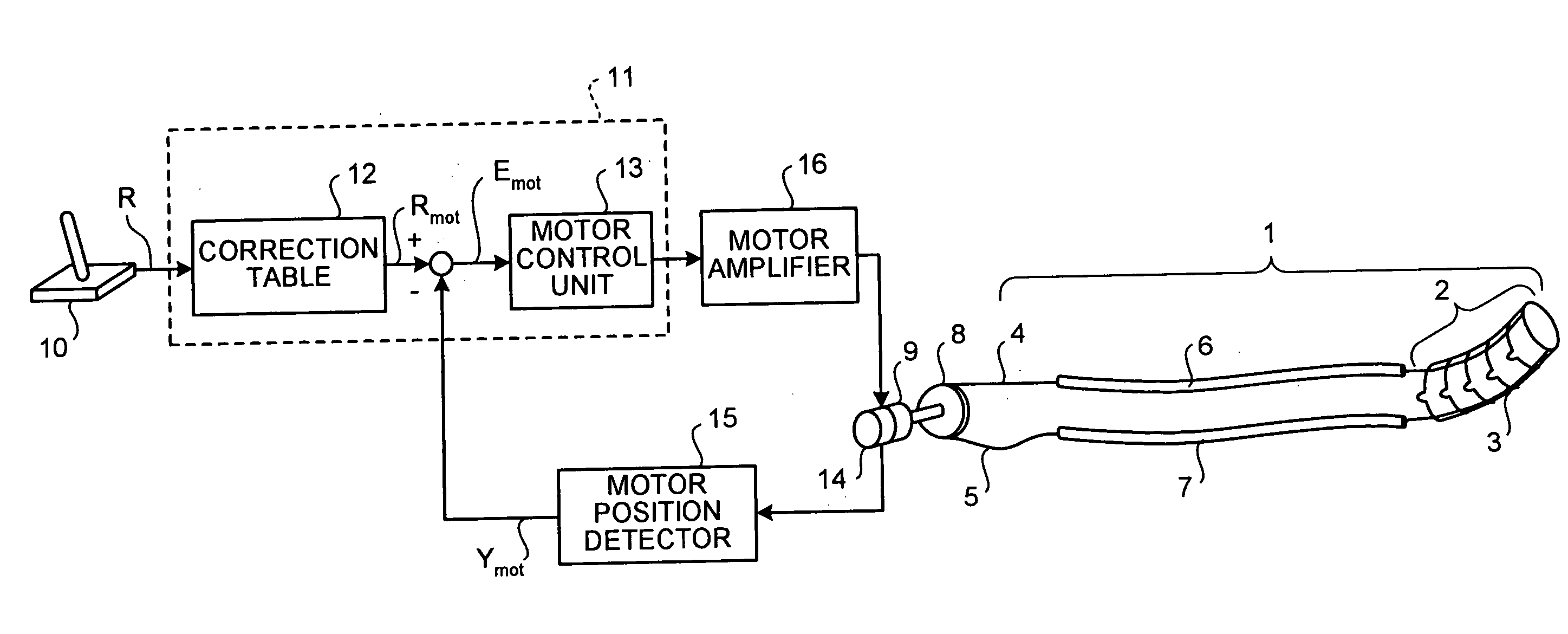
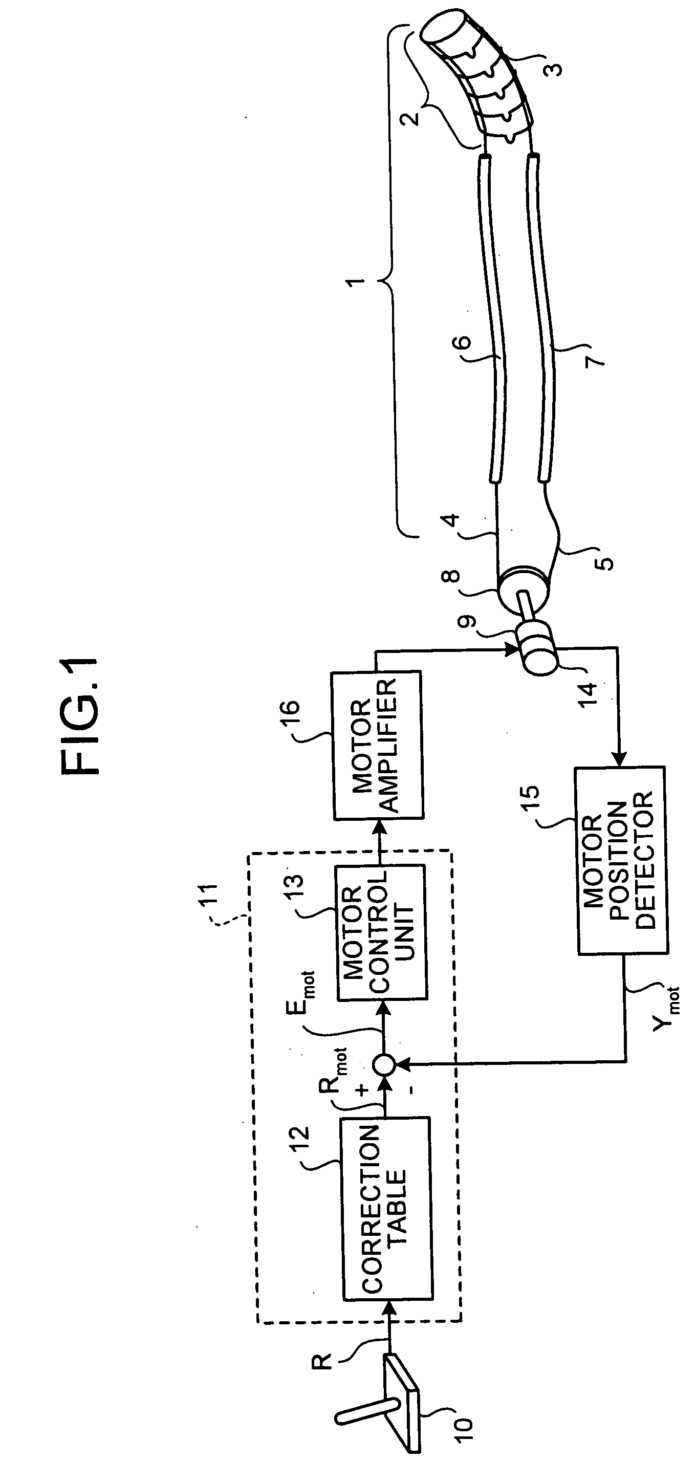
[0067] This motorized endoscope comprises a distal bending section 2 that can be bent and is a towed mechanism, wires 4 and 5 that are hauling units for hauling and bend the distal bending section 2 from both directions, a motor 9 that is driving unit that generates a driving force to the wires 4 and 5 in accordance with a control signal, a rotary encoder 14 that is a position detecting unit that detects a position of the motor 9, a joystick 10 that is an operating unit that inputs a target value, and a control device 11 that is a control unit that outputs a control signal that corresponds to the target value by the joystick 10 and that is based on a detected position detected by the rotary encoder 14.
[0068] An inserting portion 1 is formed into a thin and long shape so that the inserting portion 1 can be inserted into a body cavit...
second embodiment
[0083] (Second Embodiment)
[0084] A second embodiment of the present invention will be explained with reference to FIG. 6. The second embodiment is different from the first embodiment in the following description, and other portions of the second embodiment are basically the same as those of the first embodiment.
[0085] In this second embodiment, the operation amount of the joystick 10 is defined as a target value R' of speed of the distal bending section 2. That is, an operator designates the speed of the distal bending section 2, and operates the apparatus. In the second embodiment, an integrator 17 is provided in front of the correction table 12, and a value to be input to the correction table 12 is defined as a target value R of position of the distal bending section 2 like the first embodiment. A differentiator 18 is provided behind the correction table 12, a control signal Rmot that is output from the correction table 12 is differentiated, and the resultant is defined as a speed...
third embodiment
[0087] (Third Embodiment)
[0088] A third embodiment of the present invention will be explained with reference to FIG. 7 and FIG. 8. The third embodiment is different from the first embodiment in the following description, and other portions of the third embodiment are basically the same as those of the first embodiment.
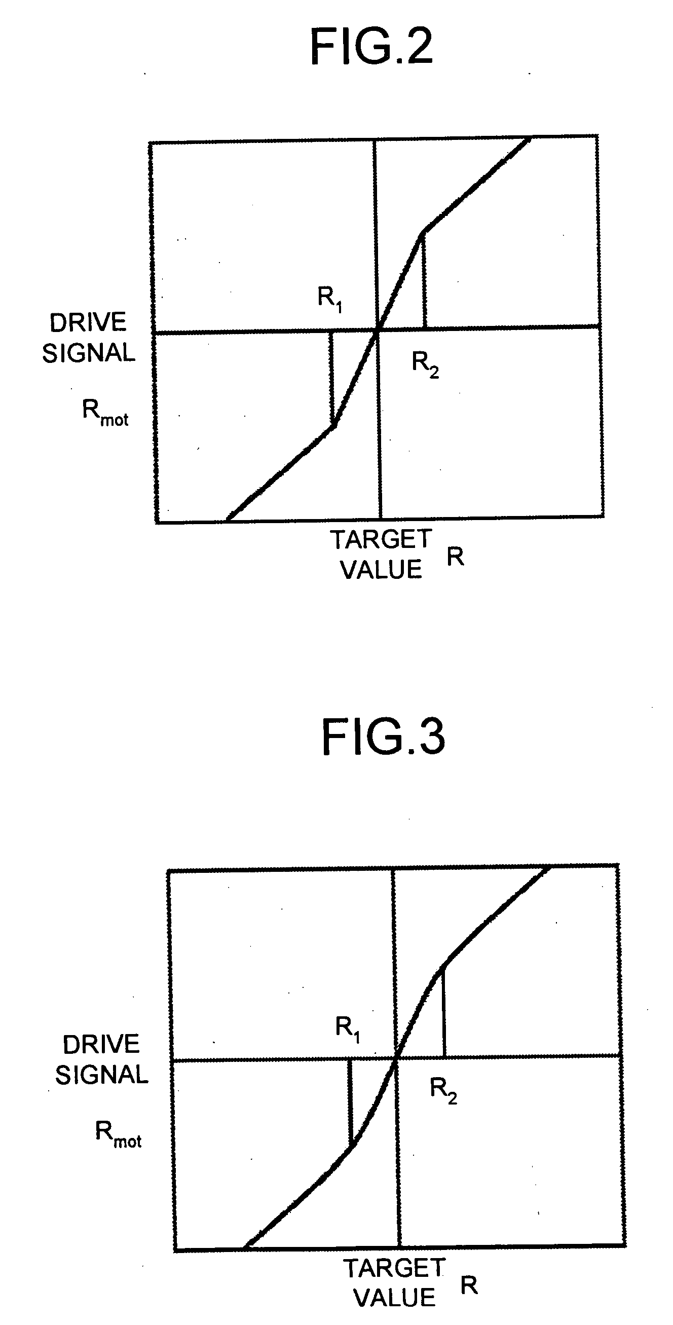
[0089] In the third embodiment, ranges R1 to R2 of the target value R at which both the wires 4 and 5 become loose is automatically renewed. In this third embodiment, tension sensors 20 and 21 are mounted to the wires 4 and 5 as illustrated in FIG. 7, and a wire tension detector 22 detects tensions T1 and T2 (both tensions are zero or higher). The renewal unit 23 renews the lower limit value R1 and the upper limit value R2 using the motor position signal Ymot and the tensions T1 and T2 of the wires 4 and 5. If it is judged that slack is generated in both the wires 4 and 5 and the motor 9 is not abruptly driven even if the lower limit value R1 and the upper limit value ...
PUM
 Abstract
Description
Claims
Application Information